Forming flange straightening
|
|
Forming flange straightening |
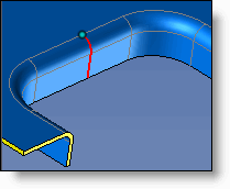
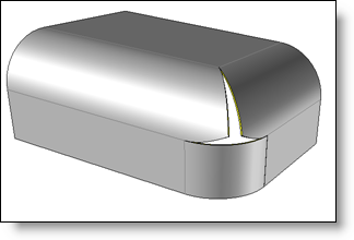
This command allows you to straighten the fallen edges and create trunk corners.
Creation stages / Use:
Click the  icon or select Sheet Metal > Forming flange straightening... from the drop-down menu.
|
|
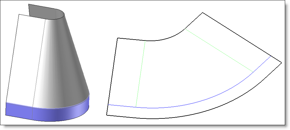
Face Straightening:
|
||||||||||||||||||||||||
|
|
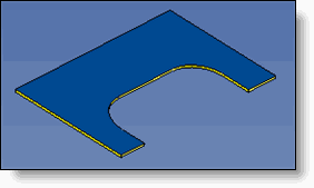
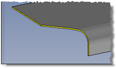
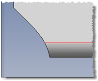
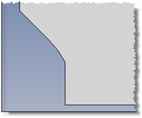
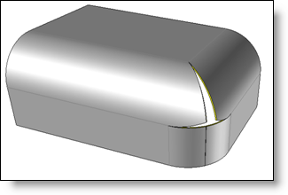
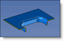
Extension on unfolding: This mode allows to define on the 3d part extension areas. They will be automatically reported on the unfolding document, without adding geometries on the 3d. Edges to extend have to be identified as well as the extended value to apply. Edges to extend can be on the boundary of the part to treat. In this case the extension will be added on the unfolding of the part to treat.
They can also be in the part. In this case, the extension will replace the area of the part identified by the operation.
|
||||||||||||||||||||||||
|
|
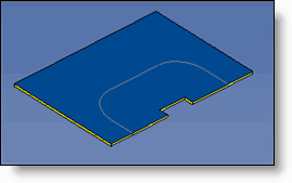
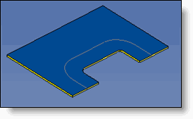
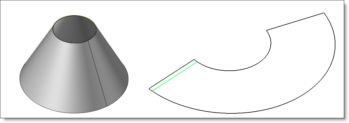
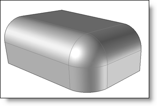
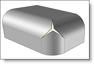
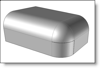
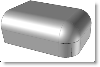
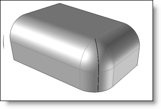
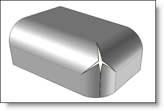
Round corner: This mode allows to create an unfolding shape of a «round corner». Several configurations are supported:
|
||||||||||||||||||||||||
|
|
In order to not work on the basic part, you can create a derived part. |
Available Options:
Keep Border Edges:
|
|
Allows you to mark the face at the location of the borders. |