Bend along a line
|
|
Bend along a line |
This command allows to bend a sheet along a line or an edge.
Creation stages / Use:
Click the  icon or select Sheet Metal > Bend Along Line... from the drop-down menu.
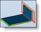
Select the face(s) to bend.
Select a bending line type (extended line, line or edge).
Depending on the chosen selection mode, select :
either a line then an edge on the fixed side of the sheet (this edge must not intersect the bending line).
or an edge of the face to bend.
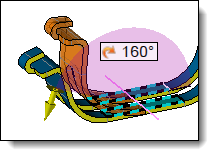
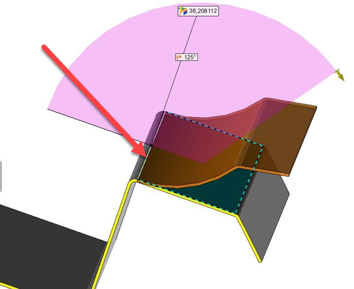
Enter the bend parameters (inner radius, angle, position).
Validate the creation of the bend with the  button.
|
|
The bending line must be created beforehand in a sketch with only one segment. |
Available Options:
Faces to bend:
|
|
You can select several faces to bend. To allow this type of bend, these faces must be coplanar: |
||
|
|
|
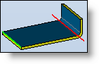
Bending line:
|
|
The bending line may be defined by a line (sketch) or an edge: |
||||||||||||
|
|
|
||||||||||||
Bend: (Only for the Line or the extended line options).
|
|
This section allow you to define the bend parameters for a bending line like Extended line or Line:
|
||||||||||||
|
|
|
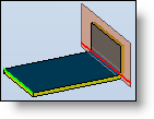
Bend: (Only for the Edge option).
|
|
Whole face: The goal is to have a rolling of the face which matches with the length of this face (by taking into account the used unfolding rule).
|
||||||||
|
|
This section allow you to define the bend parameters: it is not available if Whole face with Given angle is checked.
|
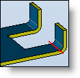
Notches: (not available for extended bending line).
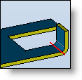
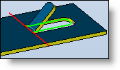
Trimming profile:
 |
Check this option to limit the face to bend by a profile (open). This profile must have two intersections with the bend line. |
|
Example: The bend line is in red, the trimming profile in green. |
|
|
|
|
|
Clearance can be indicated between the reference face of the sheet and the bent face, checking the Invert box positions this clearance inside or outside the trimming profile. |
Dimpling:
 |
Check this option to create a dimpling. |
|
Enter the dimpling height. Select the dimension position .It can be between external faces, between internal faces or a global dimension. |
|
|
A second bending radius can be entered. By default, it has the same radius than the face to bend. |
Unbending method:
|
|
Refer to the unfolding rules command for more details. |
Advanced options:
|
|
|
Modifications / Additional information: