In Place Schematic
|
In Place Schematic |
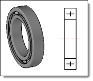
This command allows you to define entities to be used to replace the part or the sub-assembly in the drawing. This replacement is possible thanks to the advanced option Schematics projection of the main view command.
Creation stages / Use:
Select the Tools > Drafting > In Place Schematic... command from the drop-down menu.
Relaunch the command to define the schematic of the three projection directions. |
|
|
|
|
|
Available options:
In Place Schematic:
|
|
Modifications / Additional information:
It is necessary to create a schematic for each projection direction.
A schematic entity is created for each direction, in the Schematics folder of the entity tree.
The defined schematics can be visualized in the top level assembly by using the contextual command Other > Show schematics.
In the case of an assembly with schematics defined in different sub-assemblies, only the schematics of the highest level sub-assemblies are retained.
A schematic replaces the part geometry in the projection, unlike a Detailing, which adds information to the geometry projection.
 .
.