Automatic Nesting


Links / Videos :


This command allows to automatically place several Parts documents on a support with any form by entering the quantity of each part.


Creation stages / Use:


Select the Nesting > Automatic nesting... command from the drop-down menu.


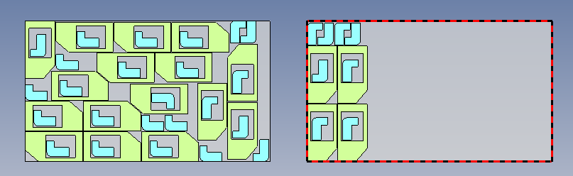
  • Complete: Parts already nested are kept where they are. It is possible to increase the asked quantity for these parts. It is not possible to decrease their quantity, their degrees of freedom and their gaps.

It is possible to add new parts, to add supports or to increase the quantity of supports.

  • Recompute: The position of the already nested parts will be recalculated by taking into account the added parts. It is possible to increase or decrease the part quantity, as well as the degrees of freedom, the security gap.

  • Cluster nesting: This mode allows to put one or many parts with the better support from the list proposed while taking account : priority order, degrees of freedom... When this mode is activated, common cut and nesting by enclosing box is desactivated. In the tab Strategy, there is different mode of packing and also ordering options.

  • Common cut: This mode allows to group parts which can be cut in the same time. When this mode is activated, a column Common cut is added in the table of parts to nest.

  • Nesting by enclosing box: This mode allows to consider only the enclosing box of each part. In this case, the security gap value is used to parallelize the enclosing box section and to create the security section. If a section is defined with the nesting characteristics operation, it is not used.

The use of the Nest into holes option has no sens. Cut-outs aren't considered.

  • Nesting with additional security area: It is possible to position the parts by defining a geometry section and a security section, which can be different from the actual geometry of the part. This security area is defined in the part by providing the Nesting Additional Security Area function. If the mode is activated, the automatic placement then takes into account this security area defined on the part.

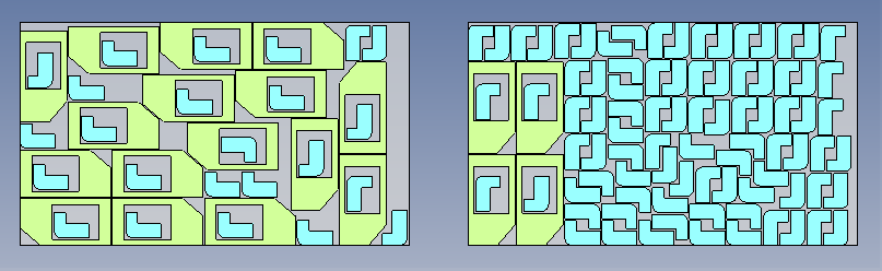
  • Maximum filling: TopSolid calculates for each part, and in each available support, the placement giving the lowest loss rate, regardless of the number of parts placed. Then it continues with the other parts by testing on the remaining supports (taking into account the priority of the parts and the priority of the supports).
  • Only the best placement is produced, with the resulting quantity of parts.


  1. Activate the Parts tab. Drag the parts to nest from the project tree.

  2. Activate the Supports tab. Drag the parts to nest from the project tree.

  3. Select the strategy.

  4. Select the options.

  5. Validate by clicking .


This command is protected by a license.


  • The parts are placed according to the absolute XY plane or following the frame defined by the nesting characteristics command.
  • It is possible to combine differents nesting modes.


The nesting window is composed of six tabs:


This tab allows to select the parts to nest by dragging them from the project tree and by filling the placing informations (quantity, gaps, rotation, ...)

  • Parts are added by drag/drop of

    • part documents into the parts list dialog.

To be able to be added to this list, a part document must be able to provide at least one nesting section (2d).

A part can be placed if it follows these rules:

  • The document provides the nesting component function. To do it, use the nesting characteristics command.

  • The detailed representation contains only one sketch (it is the case of an unfolding document). It is taken by default as section to nest.

  • The detailed representation contains only one shape. The silhouette of the part in the XY plane of the absolute plane is used or of the machinable frame if it it is defined by thenesting characteristics  command.

In each case, the section plane will be the positioning plane of the part in the nesting.

If the machining frame is defined, its X axis is used to define the 0° orientation of the part rotation angles.

    • or BOM. It allows you to:

    • Nest unbendings associated with parts in the BOM, rather than the parts themselves, taking into account the quantities of parts.

    • Nest local parts of an assembly.

    • If the BOM contains manufacturing indexes, these are transferred to the parts in the documents produced by the nesting.

  • Large priority parts: the placement priorities of the parts are determined automatically. All larger parts are placed first, then in the remaining space, the others in order of size.

  • The quantity of each part to nest can be modified. If after the calculation, a quantity is highlighted in orange, it means that the asked quantity has not been placed.

  • Priority: The nesting  takes supports with a priority of 1 (the smallest value) and places parts regarding their priorities. Then supports with priority 2 are completed with residual parts, always by considering their priorities. And so on....

Parts and supports priorities are independently considered.

  • The Filler part option indicates if it is allowed to position this part into a cut-out of another part.

  • The Nest the enclosing box option allows to use the enclosing box instead of the part geometry.

  • A Security gap can be entered. It is uniformly distributed around the contour of the part. When providing the Nesting characteristics function, a security section can have been defined.

  • The Nest into holes allows to prohibit or grant the use of cut-outs of this part to nest other parts. It can be predefined by using the Nesting characteristics function, but can be changed when you want. It is applied to every internal boundaries of the part. If a part contains a lot of small cut-outs, this could negatively influence nesting results. In the case of a part with a big cut-out (to consider) and small cut-outs (to ignor), the good way is to use the Nesting characteristics function by defining a sketch with the external boundary  of the part and the internal boundary to consider.

No: The nest into cut-outs is prohibited

Yes: The nest into cut-outs is allowed.

  • Allow flip

This option allows to flip the part on the support in order to gain in loss rate.

In order that a flip part is properly placed inside the support, TopSolid must knows its thickness. For a sheet metal part this value is retrieved automatically, otherwise it must be entered in the Nesting characteristics.

Into the nesting document, part quantity is global (flipped part or not).

  • The Degrees of freedom are allowed rotations of the part.

Free: The nesting manages the part rotation from 0° to 360° with a step of 1°.

Interval: The option allows to enter a minimum angle, a maximum angle and a rotation step. During the nesting, the part could be rotated regarding this entered step. If the minimum angle is 0°, the maximum angle is 360° and the step is 90°, the part could be rotated at 0°, 90°, 180°, 270° or 360°.

Angles: The option allows to force rotation angles of the part when nesting.


TopSolid creates a polygonization of the profiles to nest. The polygonization tolerances to arcs and lines can be modified in the document options.


This tab allows to define the list of supports to use to nest parts and the nesting characteristics (quantities, border gaps).

  • Supports are added by drag/drop of part documents from the project tree into the supports list dialog. Use the nesting characteristics command and select the Support mode.

  • For rectangular supports, it is possible to enter different border gaps (Top, bottom, Left, Right).

  • For other kind of supports, only one border gap can be entered.


This tab summarize the contain of each placing. It displays the number of included support ( a support can be included several times if the parts quantity allows it) and the loss rate. This tab is only displayed if the nesting has been calculated.


This tab allows to manage the nesting strategy.

  • Packing: Allows to define if the nested parts are on the left, on the right, on the top or the bottom of the support.

On the left: The packing is realized on the left of the support, the loss area is on the right.

On the right: The packing is realized on the right of the support, the loss area is on the left.

On the top: The packing is realized on the top of the support, the loss area is on the bottom.

On the bottom: The packing is realized on the bottom of the support, the loss area is on the top.

  • Packing: only available for the mode Cluster nesting

On the bottom left: The packing is realized on the bottom left, the loss area is on the top right.

On the top left: The packing is realized on the top left, the loss area is on the bottom right.

On the top right: The packing is realized on the top right, the loss area is on the bottom left.

On the bottom right: The packing is realized on the bottom right, the loss area is on the top left.
  • Ordering: only available for the mode Cluster nesting

Horizontal then horizontal: Parts are placed horizontally with start of each line on the same side. This means that the first part of each line will be on the top of the other.

Horizontal the vertical: Parts are placed horizontally alternating the start of each line. This means that the first part of each line will be on the top of the last part of the previous line.  

Vertical then vertical: Parts are placed vertically with the start of each line on the same side. This means that the first part of each line will be next to each other.

Vertical then horizontal: Parts are placed vertically alternating the start of each line. This means that the first part of each line will be next to the last part of the previous line.
  • 180 degrees rotation alternated by row: This command is only available in mode Cluster nesting. It allows to alternate the position of part to turn the part of 180° between each row.

  • Compact: It consists to optimize the parts nesting at the end of the calculation. this step needs system resources. parts are better packed and in some cases, more parts can be placed.

  • The entered time is the calculation time of the nesting. By entering 10s, the nesting will take 10s.

      • This time has to be adapted to the nesting complexity. An approximative measure of the complexity consists to count the number of allowed degrees of freedom (= number of parts x number of degrees for each part). The complexity of the nesting section is also taken into account.

      • It is recommended to enter a sufficient number of supports to be able to place all parts.

  • Minimize the number of different nestings: allows to reduce to the maximum number of different nestings to have the greatest possible number of identical nesting.

  • Filler parts: The limit can be defined as Offcut or Whole support.

      • Offcut: The filler parts are limited to the packing of the other parts.

      • Whole support: The filler parts can complete the support.

Offcut

Whole support


  • The check of the consistency between the material of the part and the support can be activated. If it doesn't match, the nesting can't be validated.

It is possible to allow supports and parts without material. In this case, there will be no error.

  • The check of the consistency between the thickness of the part and the support can be activated.

  • Collisions can be displayed with a specific color by using the check collisions option. This option is useful in the case of a nesting manual modification.

  • The parts with a security gaps which is not respected can be displayed with a specific color by using the Check security gaps respected option. This option is useful in the case of a nesting manual modification.

  • The Check quantity respected: This option allows you to check that the number of parts requested is identical to the number of part placed in the supports.

  • The Invalid if a problem is detected option makes the document invalid if one of the checking criterions isn't coherent (collision, non respected security gaps, wrong quantity, material, thickness, ....)


This tab allows to manage colors, default values for security gaps of the parts and the supports, for the gap between supports, the text style to use and the template to use. These defaults values and options allow to fill the new documents dragged in this nesting. If a part has a security gap defined with the nesting characteristics command, it will be used.

      • The Automatic colors allows to assign a random color to each different part.

      • The Nest the enclosing box option allows to use the enclosing box instead of the part to nest. In this case, cut-outs can't be used (filler parts).

      • The part security gap allows to define the default values for new dragged parts in the listed parts to nest.

      • The different gaps for all new dragged supports in the supports list can be filled with a default value.

      • The gap between supports can be filled by default.

      • The nesting text style can be selected or created. It is the text displayed in the nesting which indicates for example the loss.

      • An assembly template can be used. A nesting generates documents like assemblies, manufacturing, sheet metal manufacturing, ....) with a document by support and nested parts. The selected template will be used when creating the document.


The Nest the enclosing box check box and the security gap value allow only to pre-fill the new dragged parts in the parts table. By default, they will be considered as to nest by enclosing box with the given security gap. Then, it is possible to uncheck the box or to change the gap by part.


Modifications / Additional information:


For local parts nesting, drag-and-drop the assembly in the automatic nesting window, validate the question for local parts nesting and select local part to nest.

  • It is possible to nest a local part only when it contains nesting characteristics management.

  • Creating a local part, when the origin part contains nesting characteristics management, these options will be copied for each local parts. TopSolid uses options of template part at the time of the local part creation. Subsequent modifications done in the origin document will not be updated in the local part.

Details about the nesting characteristics management in the local part:

  • Representation: TopSolid uses shapes of local parts, coming from conversion or local inclusion.

  • The frame is basified et properly placed.

  • When Section to nest is set to automatic, TopSolid will keep this mode..

  • When Section to nest is set to manual, TopSolid will move on automatic mode.

  • Settings of Nest the enclosing box, Nest into holes and Allow flip are copied in the local part.

  • When Thickness option is defined, its value will be copied in the local part.

  • When Security area is activated with offset, the value will be copied in local part and the section will be computed again.

  • When Security area is not activated or activated with user section, TopSolid desable Section area and provide empty section. It means the section will be recalculated on the fly when calculating nesting operations.

  • When Freedom degrees is used, its values will be copied in the local part.

When necessary, it is possible to edit nesting characteristics of local part to modify its options. For that, change the assembly stage to Analysis and from the operations tree unfold the local part folder to edit its Nesting characteristics management operation.


To use a symmetrical part a Mirror part must be created and it must be added to the parts to nest.

When creating the mirror document, the Nesting characteristics analysis operation is derived too with the rules below:

  • For part or support:

  • When section to nest is manual in the reference document, it will switch to automatic in the mirror document.

  • For part only:

  • If there is a security area defined with manual section in the reference document, TopSolid will not use security area in the mirror document.

  • If part uses freedom degrees they will be managed in the mirror document. When freedom degrees have been set from a fonction provider Tools > Fonctions > Provide fonction > Nestable component freedom degrees..., they will be saved if fonction derivation is checked in the derivation operation.