
Guidelines for all millings
|
|
Guidelines for all millings |
Definition of Millings
You can now define millings.
Millings are grouped into three major categories.
2D milling
3D milling
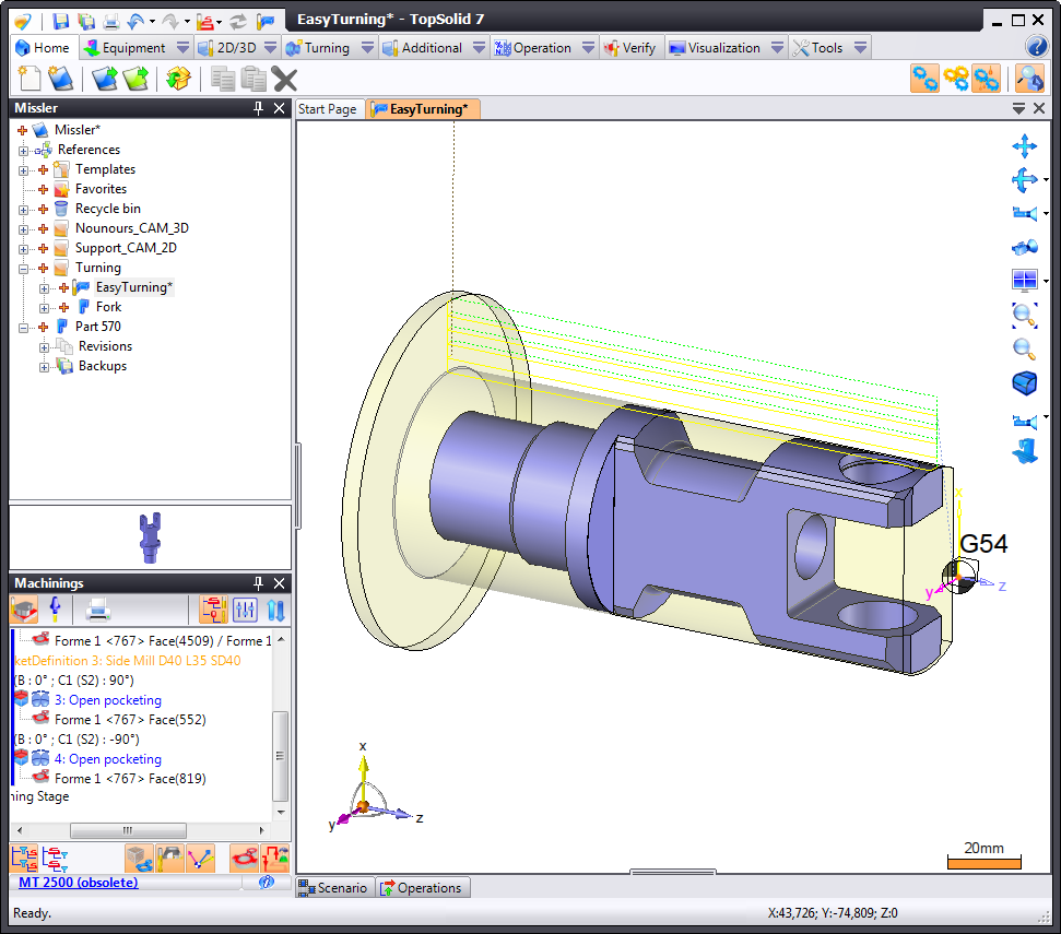
Turning
There is also a fourth group that corresponds to additional operations.
As you have seen, these millings can be called using the menu or mouse
For each milling, you must answer questions that will be explained later function by function (see help index under "Menus") or press the F1 key when you do not understand the value to enter in TopSolid.
Whatever the case, to facilitate use, all features call the same graphic interface described below.
When you wish to edit an operation, this interface will display. For purposes of simplification, you can edit as you create in TopSolid!
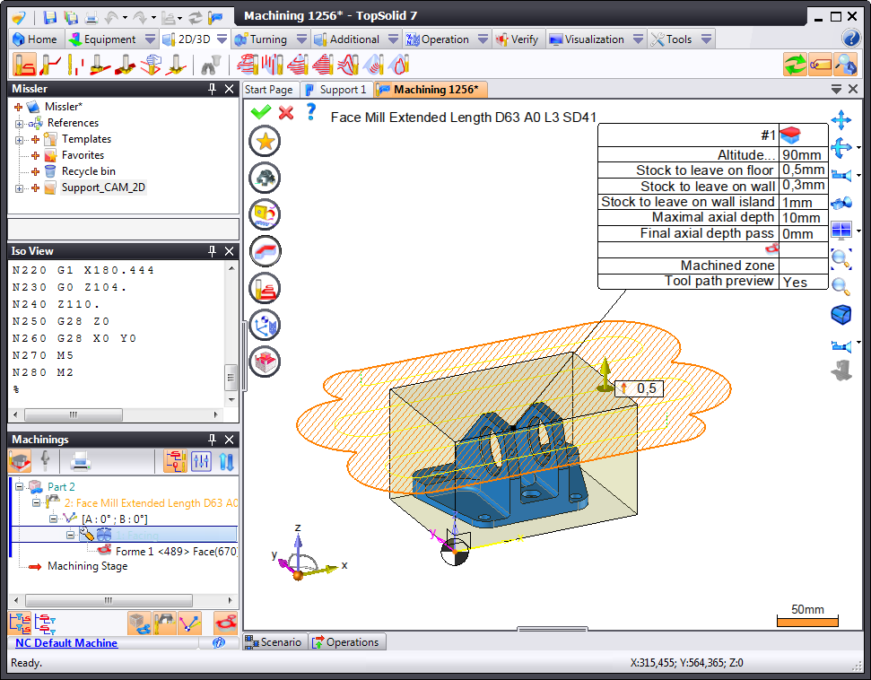
Graphical Interface
When you select the milling type, an icon bar appears as well as a label. These elements allow you to set the milling operation.
OK button ( ) is grayed out, which means that elements are missing and that you must fill them in order to confirm the command.
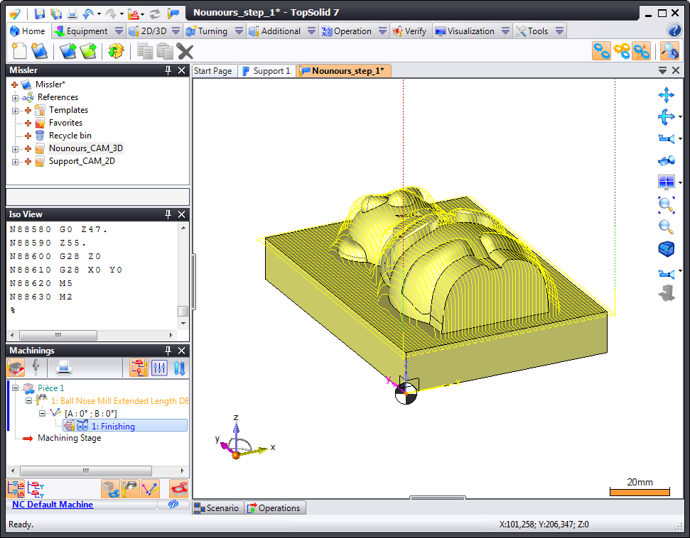
Simulation
When the milling is validated, a simulation is automatically launched with or without removing the material ( ) depending on the option selected. You can increase or decrease the simulation speed using the "+" and "-" keys.
You can also launch the simulation from the Operations Manager by right-clicking the operation.
ISO Code
Using the "ISO" window, you can view the milling operation ISO codes. If the ISO Code window is not available, you can request to view it (see the Window Management topic by right-clicking on the project window banner).