|
|
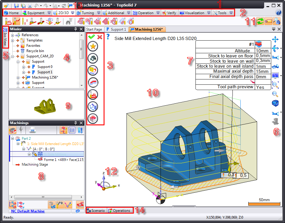
Screen Presentation |
The TopSolid'Cam screen contains several areas allowing you to manage projects and documents.
|
1 Banner |
8 Operations Manager Window |
|
2 Context and Menu Tabs |
9 Part Preview Area |
|
3 Icon Bar |
10 Work Area |
|
4 Project Window |
11 Label Preview |
|
5 ISO Program Tab |
12 Compass |
|
6 Preview and Rendering Bar |
13 Switch between Cad/Cam |
|
7 Label |
14 Scenario and CN Operations Tab |
1. Banner
The banner displays the name of the current document as well as information related to the type of PDM used
2. Context and Menu Tabs
This area displays the complete set of available commands. The menu content depends on the document type being edited as well as additional modules installed.
Click the tab text of a context to display its icons in the Taskbar located just below. This bar includes the most frequently used menu commands (you can also change the toolbar by placing the mouse cursor in this area and scrolling the wheel, if the mouse has one).
3. Icon Bar
This bar allows you to configure a milling operation by defining the "presets", tools, cutting conditions, geometry to mill, lead in/lead out settings, stocks to leave, clearances and comments.
The validation is done using the green icon.

 If information required for validating a command is missing, the software indicates this with an asterisk (
  )
)
4. Project Window
It groups all parts, millings and preparations. To launch one of these elements, drag it to the work area.
The project window belongs to a detachable tab that can be pinned to a desired location on the screen.
5. ISO Program Tab
The ISO program that corresponds to millings complete in the Operations Manager can be found on this tab.
6. Preview and Rendering Bar
The visualization and rendering bar groups the most frequently used commands from the Visualization menu. These commands allow you to quickly modify the current document.
 You can change the content of this bar using the Tools > Customize command.
7. Label
It allows you to configure operations, such as stocks to leave, axial depths and milling operation types.
Modifying the label settings also modifies the settings in the icon bar (#3). All modifications to the label are reflected in the banner.
8. Operations Manager Window
The Operations Manager lists the milling data (tools used, geometry used, operator comments, type of operations) in a directory structure or table following the selected option.
Right-click to edit, simulate, modify, reorganize or delete operations.
A  icon in front of an operation indicates that the operations must be refreshed using the
  icon.
icon.
The Operations Manager is found in a detachable tab that can be pinned anywhere on the screen.
9. Part Preview Area
This window displays a preview of the selected part.
Double-click the window to edit the part or milling operation
10. Work Area
The work area allows you to view the document being modified. The management commands for this area (zoom, orientation, multiple windows, rendering, etc.) can be found in the Visualization menu. The most commonly used commands are grouped in an icon bar named Visualization and Rendering Bar located to the right of this area.
The mouse buttons also allow you to quickly access certain commands:
Zoom: Scrolling the mouse wheel allows you to zoom in or out of the view.
Rotation: Click and hold down the middle mouse to turn the view contents.
In addition, you can indicate a rotation axis by positioning the cursor on the element (edge, segment, etc.) and pressing the Alt key on your keyboard.
Translation (Pan): Click and hold down the right mouse button to move the view contents.
In addition, you can indicate a translation axis by positioning the cursor on the element (edge, segment, etc.) and pressing the Alt key on your keyboard.
When the workspace is divided into several views, the active view has a black border and also contains the compass and preview and rendering bars.
11. State of Context
States (or modes) allow you to set options in the current context. The mode is selected when the icon is on an orange background (orange, being the default active color, can be configured in the Window topic from the Tools > Options... command).
12. Compass
The default position (bottom left) allows you to view the orientation of the absolute frame and control the orientation of each view using the various sensitive areas that become green when hovered over by the cursor. Double-click each element on the compass to apply rotations around the axes or spherical rotations.
13. Switch between Cad/Cam
This command allows you to switch from the design menu to the milling menu  . You can also use the Ctrl+W shortcut
14. Scenario and CN Operations Tab
Organization in the form of a timing chart. Allows you to simulate milling operations and display completed CN operations. The Scenario tabs displays operations based on their durations.
|
|
Information
Each user can select their own window layout and reorganize their workspace by double-clicking and moving a window banner or tab.
|