Blend
|
Blend |
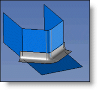
This command can create join surfaces between sets of faces
Creation Stages / Use:
Click on the icon
or choose the command Surface
> Blend... from the drop down menu (or Modeling
> Surface > Blend... in the assembly document).
The command has three ways to create a join:
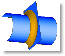
Join between faces:
|
allows to create a blend surface between 2 batches of faces. |
|
|
|
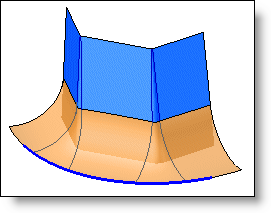
Three face join:
|
allows to create a blend face passing by 3 batches of faces. |
|
|
|
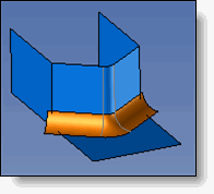
Face profile join:
|
allows to create a fillet between a batch of faces and a profile. |
|
|
|
|
To select all of the tangent faces rather than selecting them one by one, use the rotative selection on one of the faces. |
Available Options:
Section:
|
Loop: A join between ball faces is created by making the intersection of the faces a sphere. The definition of the normal for the section planes is not requested for a ball join. For a ball join with a curved section shape, you must enter a curvature value. A value of 1 is equivalent to the conical section shape. The closer the value is to 0, the more the curvature will move to the right.
|
||||||
|
|
||||||
|
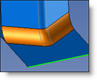
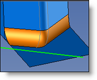
Disk: The join between disk faces results from making the intersection of faces a disk. This type of join must be defined as a guide profile for the disk. The disk's normal is defined by the tangent to a given profile. The profile must be able to define a normal at each point of the join. The green profile or edge defines normal for the section plans. The geometry of the join is directly influenced by this normal.
|
||||||
|
|
Constraints: (only for the join between faces)
|
Constraints must be given by the edges of the element. It is therefore necessary to print the constraint profile(s) to the face(s). The radius defines the maximum radius for the constrained join. It must therefore be larger than the greatest distance between the intersection of the two faces and the constraint edge. Otherwise, the constrained join will be constant for distances greater than the given radius. |
|
None: Imprinted profiles are not taken into account. |
|
|
|
Symmetrical edges: The selected printed edge will be made symmetrical with the intersection edge. |
|
|
|
Edges - Edges: The two imprinted sides will be taken into account for the join. |
|
|
|
Edges - Radius: The join will have the radius entered, and it will be trimmed by the selected imprinted profile. The radius must be less than the greatest distance between the impression and the intersection edge for the various faces. |
|
|
Advanced Options:
|
Trimming type: (only for the join between faces) defines the trimming of the join.
|
||||||||
|
|
||||||||
|
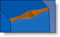
Repair auto-intersections: Makes it possible to repair self-intersecting joins. In the example below, it is not possible to make the join without activating this option. |
||||||||
|
|
||||||||
|
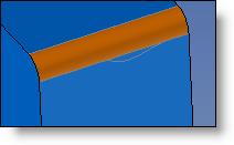
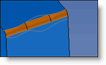
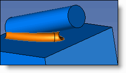
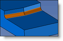
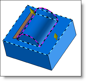
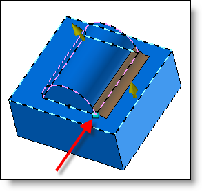
Overlap: (only for blend between faces) allows to extend the blend after an interruption in either face (pocket for example).
|
||||||||
|
|
||||||||
|
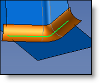
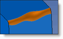
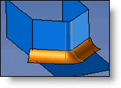
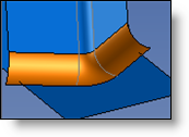
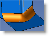
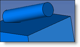
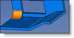
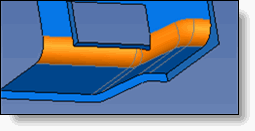
Propagate to discontinuous edges: (only for blend between faces). Allows you create the join, even if there is a square angle between faces on the same side. The input angle must be at least equal to the angle between the two faces. In the example below, just one vertical face was selected, and the entered angle was 15°. The Angular tolerance allows to enter the angular tolerance to respect during the discontinuous edges propagation. In this case, the fillet will be created only if the angle is under the tolerance limits.
|
||||||||
|
|
||||||||
|
Point: In some cases, it could be several possibilities. The point allows to select on which side applying the fillet.
|
||||||||
|
|

 .
.