This command allows you to perform a profiling
operation.
Creation stages / Use:
Choose the
Wood > Profiling... command from the drop-down menu (for a document
part or assembly)
For a Panel document, use the Modeling
> Profiling ... command.
Choose the desired mode
Plan or Fixed
Direction, depending on this choice choose a plane or a direction
in the graphic area or in the drop-down menu.
|
|
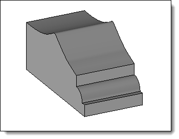
The Plane mode corresponds to machining
in which the tool axis is perpendicular to the
to the reference
face. |
The Fixed
Direction mode allows you to impose the orientation of
the tool axis independently of its
of its trajectory.
This mode is used in the case of a non-planar face. |
Select one
or more paths.
|
|
Join paths option enabled. |
Join
paths option disabled. |
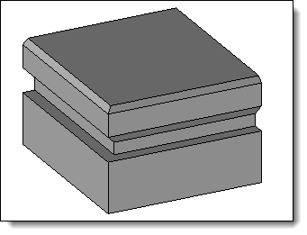
Select the
shape to be modified.
If necessary,
reverse the direction of the moulding by double-clicking on the pink
arrow.
Select a
tool model (family document), a code and then fill in the drivers
if necessary.
Opposite positioning point:
This option allows you to use the symmetrical
point of a predefined positioning (relative to the tool axis).
Opposite
positioning point deactivated |
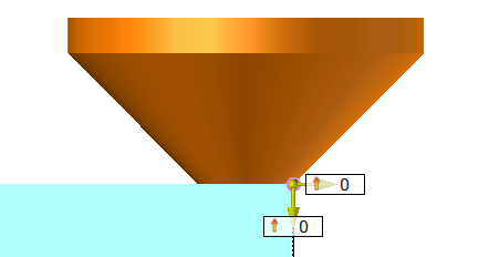
Opposite
positioning point activated |
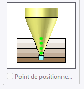
This option is grayed out when the predefined
positioning point(s) is (are) aligned with the tool axis.
Lightweight
:
Specific moulding operations can be very time-consuming.
To optimize these calculations, the lightened mode allows you to deactivate
the complete modelling of the operation, while generating only the information
required to generate the toolpath (MF).
Available options:
|
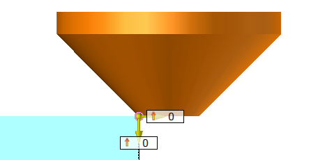
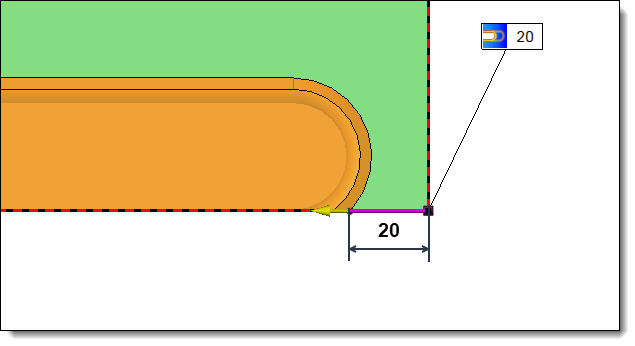
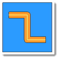
Allows you to define an input and/or
output limit at the ends of the slot.
This limit can be positioned relative
to the tool axis or relative to the tool edge.
|
|
20mm entry or exit limit
positioned in relation to the edge of the tool |
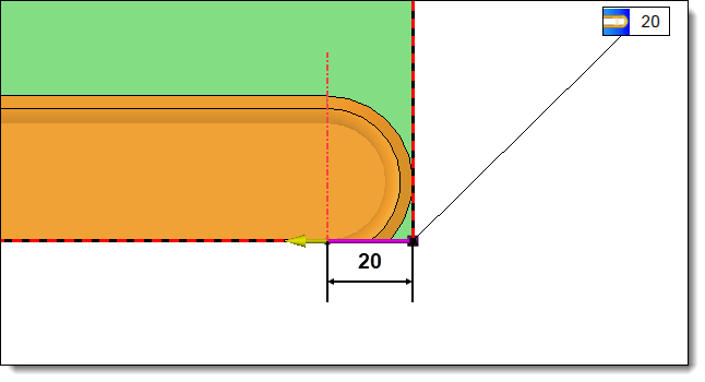
20mm
entry or exit limit
positioned in relation to the axis of the tool |
|
|
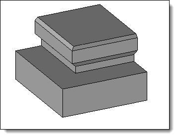
Rounded
corners:
|
Allows
you to enter a lateral offset to the profiling operation.

|
|
With
Rounded Corner
option not activated |
With
Rounded Corner
option actived |
|
|
This
option allows you to assign a machining process to the
operation. This machining process can then be retrieved
in a machining document.
1.Select
a machining process document from the drop-down list.
2.Choose
a process from the drop-down list. |
|
Changes / additional information:
To view MFs, activate the Create MF icon available from the Home tab.
An MF folder is then created in the entity tree, it is necessary to check
the cell in front of this folder to display them on screen.