- The exception can be done for one element only (part or sub-assembly).
- Once an automatic exception has been applied to a view, it is no longer possible to apply a manual exception (and vice versa).
|
Automatic exception |
This command allows to apply an automatic exception to a view in order to highlight a part or a sub-assembly within a view of the parent assembly or a higher-level assembly. It can be used on a view of a drawing model for multiple draftings.
Creation stages / Use:
Select the Automatic exception... command from the context menu on a view or a set.
Select the set containing the entity you want to highlight (the main assembly).
Select the exception style to apply.
|
|
Modifications / Additional information:
Method for preparing a drafting model with different views of an occurrence and a view where this same occurrence is highlighted in the parent assembly:
Create a view with this secondary set.
Modify the rendering mode of this view to configure its main render mode and its secondary render mode (which will be used by the exception).
Create an exception style to adjust the attributes of the occurrence to be highlighted (line type, secondary render mode, etc.).
Activate the Automatic Exception via the context menu on the view or on the second set (the exception will be applied to all views consuming this set).
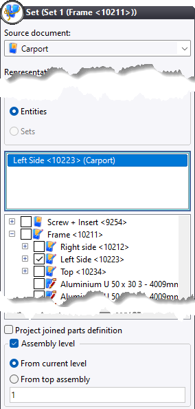
Reference set: select the main set.
Exception style: select the style created previously.
Optionally, create a layout sketch and switch the scale of your exception view to absolute scale (to optimize the layout of the views).
Clear the sets by editing them and selecting <unspecified> in the Source document field.
Save the template.
This template can, for example, be used in a multiple drafting from a bill of materials. Thus, all selected occurrences will appear individually in the views of the main set and will be highlighted with a higher-level assembly in the view of the secondary set, the one containing the automatic exception.
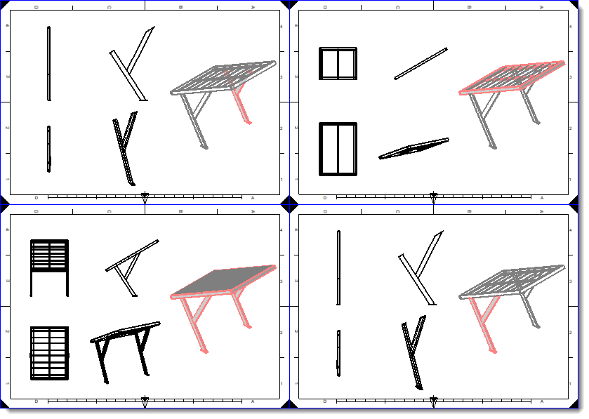
Example of use:
|
|
Configuration of the secondary set. The goal is to display the parent assembly (n+1)in the exception view. |
An exception style with shaded secondary rendering and thick red lines has been configured. A drafting has been made for the occurrences Right side, Left side, Top, and Frame. The assembly level setting, as shown on the left, means that the exception view of the Right side, Left side, and Top subassemblies contains the Frame assembly. And the exception view of the Frame subassembly contains the Carport assembly (with solar panels). |