
|
Select
the  Profiles
mode to place the command in profiles mode: Profiles
mode to place the command in profiles mode:
- Heigth
to cross: distance
between the floor and the landing.
It is possible to give this Length or to select a Point
in the graphical environment to determine this height in relation
to the destination frame.
The
lines correspond to the flights,
the arcs to landings. Two
consecutive lines allow the inclusion of a Classic
landing between two flights. The
profile is oriented, which defines the direction of ascent.

|
The
profile must be created in an XY
plane, not necessarily absolute. It
must be G1
continuous and contain only lines
and arcs. |
|
The
trimming profiles must be created in an XY
plane, the same as the plane of the of the treading
profile. The
profiles must allow the limitation of treads. If the
treads cross each other, it will not be possible to
create the staircase in 3D!
|
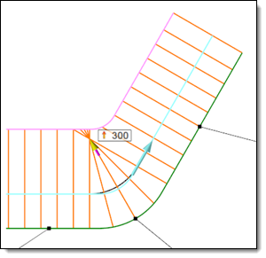
|
The center of the spiral
treads is inside
the two limiting profiles. The treads cross
each other, so they cannot be
built in 3D. |
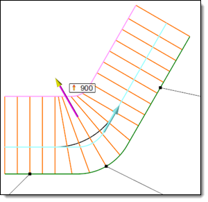
The
center of the spiral treads is outside the two limiting
profiles. The treads not cross each other,
so they can be
built in 3D. |
|
|


