
3D Contouring
|
3D Contouring |
Icon Access: ![]()
Location: 2D/3D\3D Contouring
Development:
Create a tool path that follows a non planar curve. The trajectory may eventually be projected onto the part so that the tool is in contact with the part and the curve.
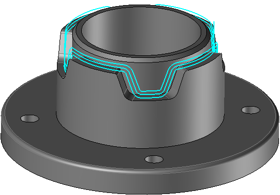
3D contouring can be done by only pressing the curve or by simultaneously pressing the curve and the part.
Based on the needs of the operator, the tool can be positioned to the left, the right or on the guide curve (by looking at the curve in the direction of the tool axis).
In 'Follow Curve' mode, the altitude of the drive point of the tool is defined by the curve itself.
In 'Follow Part' mode, the tool remains in contact with the finished part.
From the 2D/3D menu or using the mouse (by selecting or not selecting a face with the right mouse button), select the "3D Contouring..." menu.
A toolbar appears on the left of the screen, along with a label in the graphic area.
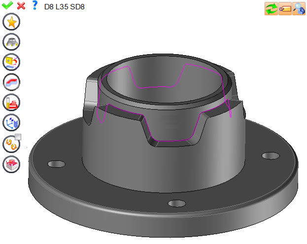
You can then modify values by
By selecting the value to modify in the label. The label is the table shown in the image in the top right corner. All label values are fields available from one of the icons in the left section. These values are placed on the label for quicker access.
By selecting the values in the graphic area or by pulling the arrows. As with the values of the labels, these fields are present in one of the left section icons. These values are placed in the graphic area for quicker access.
By opening one of the left section icons.
|
Select Favorite
Instead of modifying n values, this option allows you to restore (or save) values that have already been entered.
|
|
Select the tool to use
By default, if the previous operation tool can be used, it is reused for this operation (the name of the tool appears in the graphic area next to
If the previous tool is not suitable or if this is the first operation, you must select a tool to validate the operation (
|
|
Define Cutting Conditions for Operation
Use this icon to modify the cutting conditions of the current operation.
|
|
Define or Add Geometries to Machine
By first selecting the geometry and calling this function with a right click of the mouse, this geometry is automatically added. So it is not necessary to access this icon to do this.
Define Milling Boundaries
You can also apply trims (XYZ or contour) to the current operation.
|
|
Define all milling settings
Each milling has specific settings. Use this icon to access all settings (such as stocks to leave, altitudes, plunge modes, milling modes, etc.)
|
|
Define ISO File Settings
Use this icon to define which comment to use for the ISO code or to decide which inclined plane matrices to use.
|
|
Define colinear axis
This icon is available only if the current machine has colinear axis.With this icon it will then be possible to choose the axis drives by the operation.We also can choose the Z value of the fix axis.
|
|
Allow us to add one or more axis on the current machining
With this icon it is possible to make radial, axial or tilt a machining.
|
|
Define Operation Properties
Use this icon to define whether you would like to update the stock or calculate the result later.
|
|
Confirm
To confirm the current operation, press this icon right-click outside the window and use the "OK" menu
|
|
Cancel
If you wish to cancel the operation, click this icon.
|
|
Preview
Display or hide the machining area. When this is hidden, this area is not calculated, and response times improve.
|
|
Show Label
Allows you to display or hide the graphic area label.
|
|
Editing Update
Each time a setting is changed (such as the axial depth), all calculations for updating the hatching area and the trajectory are triggered. The setting change may take a few moments. In several cases, settings must be modified before updating the calculations. For this, press this icon. In the case, the hatching area and trajectory (for example) are not recalculated before pressing this icon again.
|
 Click the different areas in the image below
Computing Tolerance |
|
Contouring Calculation Type |
|
Machining Side |
|
Visibility management when editing the operation: click on the icons below
Machine visibility |
WCS visibility |
Tool visibility |
Collision visibility |
Stock and finish visibility |
Tool paths visibility |
|
|
|
|
|
|
|
Also allows to engrave by using the "Follow Part" mode in the operation |


 )
) )
)


