Definition of a custom chip breaker document
With this document we can define a new sequence of chip breaker.
Putting this document in a user library allows us to access to this document in all the projects.
Creation of a special document type "Custom chip breaker".
| New document |
Type : |
Common Advanced Special |
Custom chip breaker |
Cutting conditions |
Report definition |
Enumeration |
Environment
2D function |
|
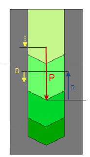
In this document we are going to define the steps to realize a set of drillings.
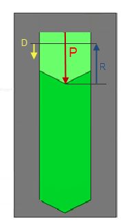
Each drilling with a depth (P)can contain an ascent (R)a descent (D) a dwell, or a rotation direction.
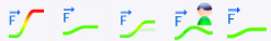
A first set of icon allows to define the action to realize.
Ascent Descent Machining Dwell Rotation direction Coolant |
We must then select between one of those 6 actions and define its parameters.
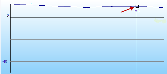
To validate and create an action click on the icon  a color graph allows to simulate the action.
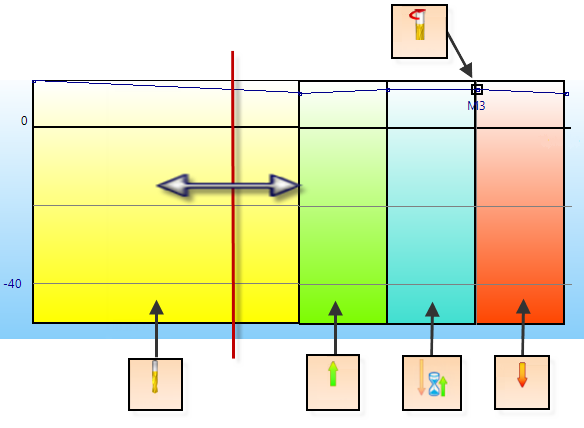
The following example shows a sequence of 5 actions: "Machining", "Ascent", "Dwell", "Rotation direction" and "Descent".
Description of the 6 actions:
 |
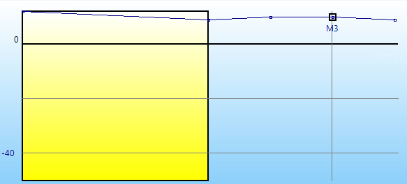
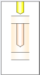
Machining :
This option allows to create a drilling with a customized depth.
 |
Offset
The distance is relative to the tool position, the depth to be achieved is added incrementally. |
 |
Altitude hole top
The distance is defined by absolute values, while the machining altitude is based on the top position of the stock. |
 |
Botoom cylindrical part
During machining, the altitude reached by the tool is calculated in relation to the bottom of the cylinder. |
 |
Full tool, including cone
During machining, the altitude reached by the tool is calculated in relation to the tool tip. |
 |
Driven point
During machining, the altitude reached by the tool is calculated in relation to the driven point position. |
 |
The depth is expressed as a percentage of the diameter of the tool used to machine the hole. |
 |
The depth is defined by a hole depth percentage |
 |
The depth is not linked to the hole, it's a defined value in mm.
However the sum of the depths must be less than the actual total drilling depth. |
 |
The depth is expressed in percentage of the total machining depth. That is the depth of the hole with stock included more safety distance. |
 The color code in the graph is yellow The color code in the graph is yellow
|
 |
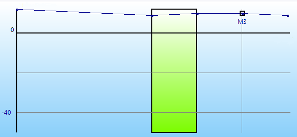
The retract :
This action allows to realize an ascent in Z.
 |
Retract plane
The altitude is the clearance plane defined in the drilling operation. |
 |
Clearance Distance
It is the clearance distance defined in the drilling operation. |
 |
Offset
This value is defined in relative in the action of "Ascent". |
 |
Altitude hole top
This value is defined in relation to the highest point of the hole (i.e. the highest point between the finish and the stock). |
The color code in the graph is green.
|
 |
Dwell :
This option allows to create a delay.
The color code in the graph is blue.
|
 |
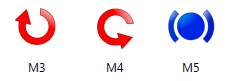
Rotation direction :
This action allows a rotation direction change or a spindle stop.
 Spindle rate factor Spindle rate factor
When the box is checked it is possible to define a factor to apply on the initial spindle rate defined in the cutting conditions of the operation.
 Spindle rate factor Spindle rate factor
When the box is unchecked it is possible to define a custom spindle rate.
The direction change is symbolized by a point in the graph with a reminder of the code.
|
 |
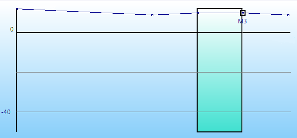
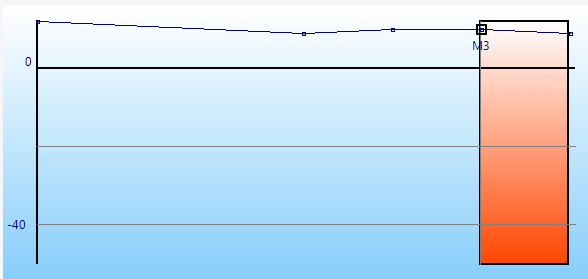
Plunge :
This action allows to realize a plunge in Z.
 |
Reach safety distance
The descent is realized until the stock + safety distance. |
|
Offset
This value is defined in relative in the action of "Descent".
|
 |
Clearance Distance
The descent is realized following the safety distance value defined in the drilling operation. |
|
Altitude hole top
The distance is defined by absolute values, while the machining altitude is based on the top position of the stock. |
|
Bottom cylindrical part
During descent, the altitude reached by the tool is calculated in relation to the bottom of the cylinder. |
|
Full tool, including cone
During descent, the altitude reached by the tool is calculated in relation to the tool tip. |
|
Driven point
During descent, the altitude reached by the tool is calculated in relation to the driven point position. |
The color code in the graph is red.
|
 |
The coolant :
It allows to activate or not the coolant with the desired mode.
There are two solutions for this.
The first is done using standard coolants and pressures.
A total of 5 coolant types can be used with a defined pressure in bar.
|
None Jet Mist Center Micro lub Air |
The other solution is to reference a customised coolant and pressure document, already created beforehand.
Coolant
Related coolant document
Custom coolant |
After adding a coolant step, it will not be possible to change the related coolant document linked to the custom drilling document, so all the coolant steps added must be deleted. |
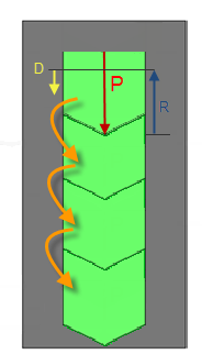
The "Loop" option allows to repeat a sequence from a step to another one to have the drilling fully machined.
|
It allows to add an action at the end of the sequence.
Select the type of action, set the parameters and click on the icon to add it. |

|
It allows to add an action in a sequence.
Click in the board of the actions to select the position, define the type of action and the parameters then to click the icon. |

|
It allows to delete a step.
Click in the board of the actions to select the action to be deleted, then to click the icon. |

|
It allows to modify a step.
Click in the board of the actions to select the action to be modified, then to click the icon. |

|
Configuration
 |
It allows to set the characteristics of the hole, altitudes and feed rates for the graph. |

|
Allows to switch from a blind hole to a through hole. |

|
Allows to resize the preview. |
|