A method document defines a sequence of multiple commands to automate
modeling tasks, resulting in significant time savings for repetitive modeling
processes.
|
We want
to create a method with the following operations:
To simplify the positioning of these operations, we will use
a constrained frame.
|
|
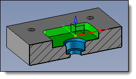
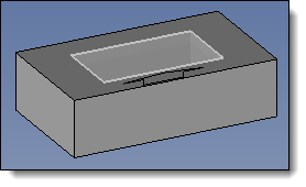
Create a new part document
containing an arbitrary shape. Place a constrained frame on
its top face - Create a sketch on the XY plane
of this frame, with the origin at the frame's origin and its
Y-axis as the vertical direction.
- Create a parallel profile to this
sketch and declare these 4 segments as construction elements.
- Make a pocket from the inner profile.
- Create a drilling group from the
4 vertices of the parallel profile (with a tapped hole diameter
of d_tapped_hole=8mm).
- Create a spot facing hole from
the constrained frame, using the bottom face of the pocket
as the starting face (with spot facing diameter of d_spot_facing=20mm
and hole diameter d_spot_facing/2).
You also have the option to create machining
processes documents to associate colors with the operations.
Note that the coloring
operation is not managed by the method.
|
|
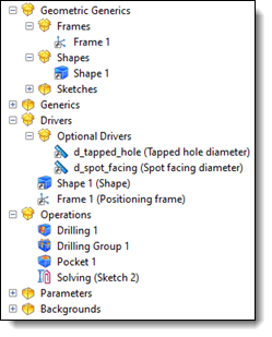
Create a new Method
document and set the part document as the generic
document. From the entities tree, drag
Shape 1 from the Geometric
Generics folder into the Drivers
folder. Also, drag Frame 1 into the
Drivers folder (you
will notice that it is automatically removed from the Operations folder). Drag the parameters d_tapped_hole
and d_spot_facing
from the Generics
folder into the Optional
Drivers folder. By double-clicking on these
drivers, you can add a designation (text that will be displayed
in the dialog when applying the method). Save your method document.
|
|
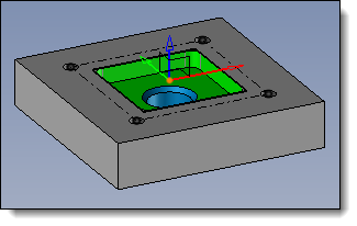
Create a new part document
and create an arbitrary part within it. Drag and drop your method document
or use the Tools > Apply Method
command. - Select the shape and place the
constrained frame dynamically.
- Modify the driver parameter values
if necessary.
- Validate the dialog.
- Repeat the method application
as needed.
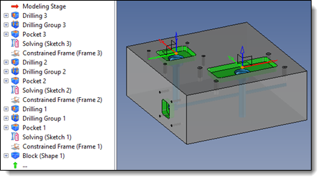
We observe that the operations are recreated in the operations
tree. They can be modified at will (for example, to change the
dimensions of the pocket).
Depending on the data entered for the drivers, observe the result
in the Parameters folder
of the feature tree (see the driver management in the  box above). box above).
|
Example of creating and using a method with entity
to basify to exclude it from method operations:
|
Method
for creating, in an assembly, the housing of one part within another.
|
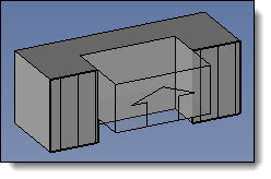
|
Create a new part assembly
document. Create an arbitrary block envelope. Create a sketch on the top
face of this block envelope (with dimensions larger than the
block envelope). Change its attributes to a
yellow color. Create an in-place part and
extrude the yellow sketch in the Z- direction. Create a sketch on the top
face of the block envelope and project the edges of this face
(gray sketch). Make a trim by profile operation
between the gray sketch and the in-place part.
|
|
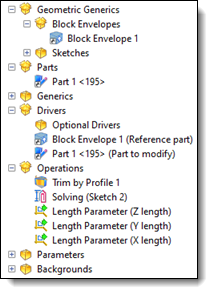
Create a new Method
document and set the assembly document as the generic
document. From the entities tree, drag
the block envelope from the Geometric
Generics folder into the Drivers
folder. To be able to select the part
you want to trim, also drag the part from the Parts
folder into the Drivers
folder.
We can see that the sketch that was
used to create this part remains in the operations folder. Keep
it in this state.
From the entities tree, drag
the block envelope from the Geometric
Generics folder into the Drivers
folder. By double-clicking on these
drivers, you can add a designation (text that will be displayed
in the dialog when applying the method). Save your method document.
|
|
Create a new assembly document
and create 2 parts, one inside the other. Drag and drop your method document
or use the Tools > Apply Method
command. Select the small part as the
driver for the block envelope. Select the large part as the
part to modify. Validate.
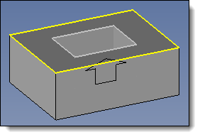
The trim has been successfully applied, but the yellow sketch
from the generic part appears because it is constructed on the
block envelope, which is a driver of the method.
It is unnecessary and clutters the assembly.
|
|
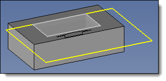
Go back to the method’s generic
document. From the Sketches
folder of the entities tree, right-click on the yellow sketch
and select the Sketch >
Others > Basify command. Open the method document and
observe that this sketch is no longer present in the operations
folder. Save the method document. Apply this method again in
an assembly and notice that the yellow sketch is no longer
created. |

