Fill hole
|
Fill hole |
This command fills holes in any position (included in the surface or beyond a border).
Creation Stages / Use:
Click on the icon
or choose the command Surface
> Fill Hole... from the drop down menu (or Modeling > Surface > Fill hole...
in the assembly document).
Select the hole's border edges.
Choose the method to use to build the surface.
Fill in the additional information, depending on the chosen method
Validate with  .
.
|
The result is an operation on the shape, which returns the border edges. No new shape is created in the shape folder in the entity tree. |
Available Options:
Hole edges:
|
This option lets you define edges that define the limits of the hole. By default, the entire detected edge loop is automatically selected.
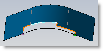
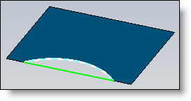
If the hole to fill is on the border of the surface, there are other possible ways to make a selection.
Use rotative selection to select a single edge rather than the entire loop. The profile option is then available. In addition to the edge, select a profile to define the closed trimmings.
Example:
Click the You must then select one of the path's edges and the two end points for the path. Confirm your selection. Next, select the profile and the edge path to define the closed trims.
Example:
|
Method:
|
This option allows you to choose the method used for creating the surface. There are several available methods:
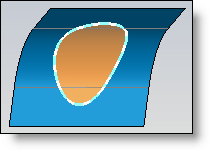
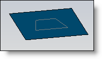
This method allows to fill the hole thanks to one or several surfaces created automatically. The filling ends at the limits defined by the selection of the hole edges.
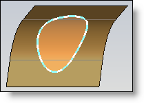
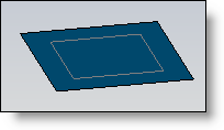
This method does not work for surface border holes. Only the hole's edges must define a closed contour. With this method, instead of getting a filling inside the limits, you get an extended surface up to the limits of the neighboring faces.
Example:
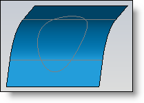
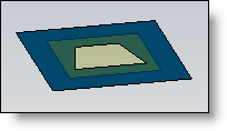
With this method, the hole is plugged using an initial surface, which the user selects using the "Shape Filling" option. The surface is trimmed at the edges of the hold and then sewn to the main shape.
With this method, the hole is plugged using an initial surface, which the user selects using the "Shape Filling" option. The main shape is trimmed by the surface edges that were then sewn.
Example:
|
Continuity:
|
This option is only available with the "Fill" method |
|
|
|
|
|
|
None: no tangency or curvature constraint is used on this edge. |
|
|
Tangency: the surface will be tangent with the neighboring face along this edge. |
|
|
Curvature: the curvature radius of the neighboring face is used to define the curvature of surface. |
Special edges:
|
This option is only available with the Fill method. it allows to define specific continuity on some edges of the hole:
|
Minimal division:
|
This option is only available with the Fill method. It allows to minimize as far as possible the number of faces generated by the filling. |

 button,
and select the "
button,
and select the "