Profile on profile deformation
|
|
Profile on profile deformation |
This command allows to create a deformation by replacing a profile on a shape by another. This deformation will be listed and usable by the deformation command.
Creation stages / Use:
Click on the icon or choose the command Construction > Deformations > Profile on profile deformation... from the drop down menu.
Select the plane the two profiles belong to.
Select the source profile. In the example bellow, the selected curve is the longitudinal edge on the selected plane.
Select the destination profile. In the example bellow, it is the spline.
Select the deformation type.
Validate by clicking  .
.
|
|
|
|
|
|
|
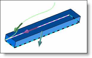
Selection of the normal plane and the curves: The plane selected in blue, the source profile in pink and the destination profile in green. |
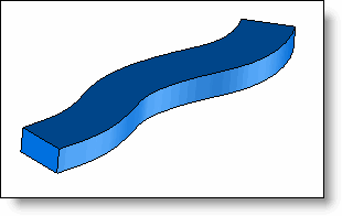
Deformed part |
|
|
The arrow on both profiles must be on the same direction. |
Available Options:
Deformation type:
|
|
|
|
Normal projection: Shape faces are normal to the destination profile. |
Parallel projection: Shape faces are parallel to the projection direction. |
Display:
|
|
A preview of the resulting position of these selected sample points is displayed. |
Modifications / Additional information:
Each modification can be done using the popup menu from the operations tree.
It is possible to replace a deformation by another (for example a flexion by a torsion), by using the Replace contextual command in the operations tree.