This command allows you to perform a profiling
operation.
Creation stages / Use:
Choose the
Wood > Profiling... command from the drop-down menu (for a document
part or assembly)
For a Panel document, use the Modeling
> Profiling ... command.
Choose the desired mode
Plan or Fixed
Direction, depending on this choice choose a plane or a direction
in the graphic area or in the drop-down menu.
|
|
The Plane mode corresponds to machining
in which the tool axis is perpendicular to the
to the reference
face. |
The Fixed
Direction mode allows you to impose the orientation of
the tool axis independently of its
of its trajectory.
This mode is used in the case of a non-planar face. |
Select one
or more paths.
|
|
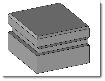
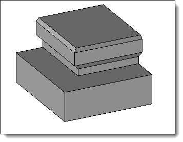
Join paths option enabled. |
Join
paths option disabled. |
Select the
shape to be modified.
Select a
tool model (family document), a code and then fill in the drivers
if necessary.
Opposite positioning point:
When this point is not positioned on the tool
axis (otherwise the box is grayed out) it can be opposed symmetrically
with respect to the tool axis.
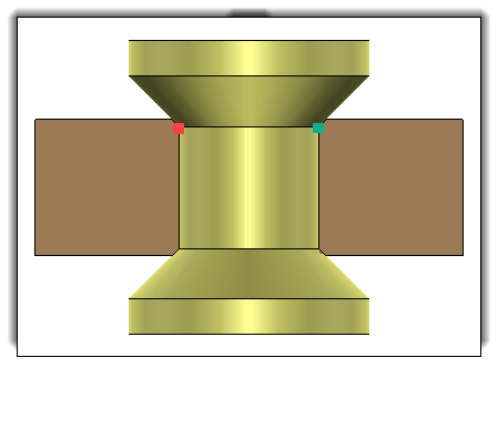
Opposite
Positioning Point option enabled with the red dot, and
Opposite Positioning Point
option disabled with the green dot. option deactivated with the
green dot. |
Available options:
|
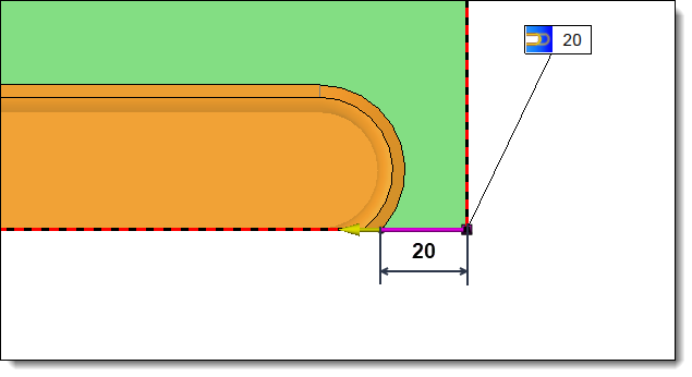
Allows you to define an Entry
limit and/or an Exit limit
at the ends of the slot. This limitation can be positioned in
relation to the tool axis or in relation to the tool edge.
|
|
20mm entry or exit limit
positioned in relation to the edge of the tool |
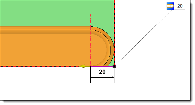
20mm
entry or exit limit
positioned in relation to the edge of the tool |
|
|
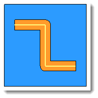
Rounded
corners:
|
Allows
you to enter a lateral offset to the profiling operation.

|
|
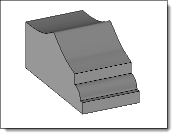
With
Rounded Corner
option not activated |
With
Rounded Corner
option actived |
|
|
This
option allows you to assign a machining process to the
operation. This machining process can then be retrieved
by TopSolid'Cam. It can also assign a color to the operation.
1.Select
a machining process document from the drop-down list.
2.Choose
a process from the drop-down list. |
|