Baffle Lines Distribution Wizard


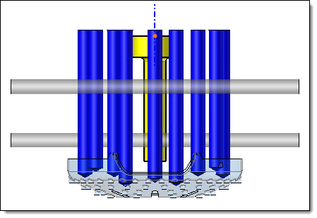
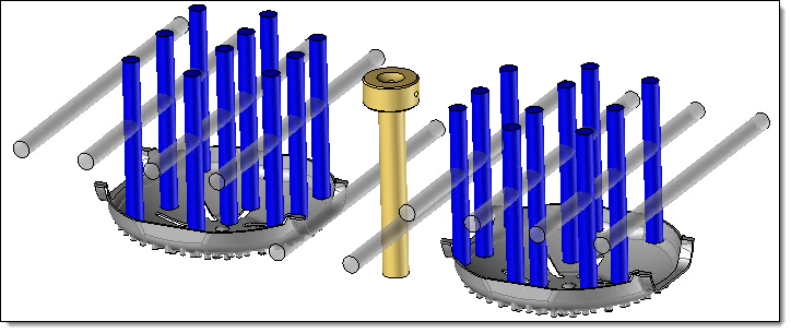
This command distributes baffle lines over profiles.  The baffle lines distribution area is defined by a silhouette with a margin of the parts of the To mold set. The holes are distributed with a minimum distance between each hole, while surrounding elements to cool (pink) and avoiding selected elements with a margin (yellow).


Creation stages / Use:


Click the  icon or select the 3D Sketch > Cooling > Baffle Lines Distribution Wizard... command from the drop-down menu. It is also possible to launch it from the context menu.


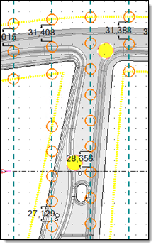
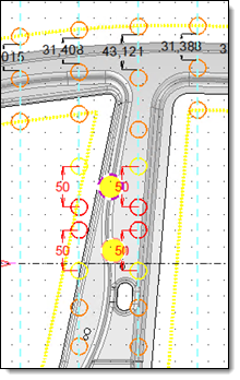
  1. Select the profiles and the margins defining the distribution of drillings on the profile.

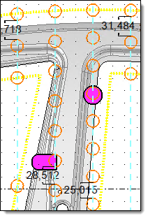
  2. Define the elements to be cooled with a surrounding distance.

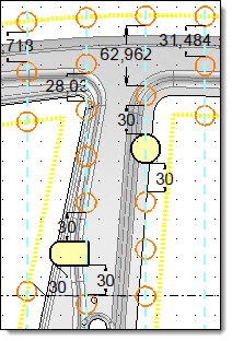
  3. Select the elements to be avoided with their safety margin.

  4. Validate .


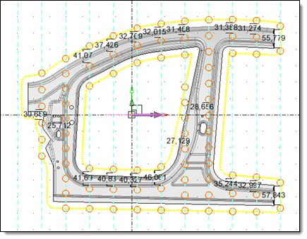
The wizard calculates a distribution of Baffle line points on a profile.  

  • This command produces a sketch and a drilling is created for each segment of this sketch.
  • It is not possible to modify this distribution via the command. Modifications are made directly by adding/modifying/deleting constraints in the sketch.


Available options:


  • Profiles : Select the profile on which to distribute the Baffle line.
    Here, the profiles are dotted in blue.

  • Minimal distance between 2 Baffle lines:  This distance defines the minimum margin to be respected between each baffle line along the profile.

  • Silhouette margin: The  baffle line distribution zone is defined by the silhouette of the part, plus a margin.


If the distribution profiles of the baffle lines are parallel to each other:  

  • Axes : The parts to be cooled are defined by their rotation axis. This axis must be in the same direction as the baffle lines.

  • Surrounding distance: Four baffle lines are created, surrounding each element. The surrounding distance has priority over the margin between two holes.

  • Strict : It can happen that the surrounding distances between several parts to be cooled are too close, or that holes overlap. The strict mode warns the user of the problem and prevents the command from being validated. By unchecking the option, holes that  do not respect the constraints are created, leaving it up to the user to modify their position or not. If two holes coincide, a single hole is created.

  • Principal direction: The direction is pre-filled with a direction perpendicular to the distribution profiles. This allows us to find the first profiles to receive surrounding baffle lines in this direction.


Distribution of baffle lines without elements to cool.

Distribution of baffle lines with taking in account elements to cool (in yellow).

The parts to cool are too close to each other to be surrounded and at the same time respect the minimum distance between baffle lines.


If the distribution profiles of the baffle lines are parallel to each other:

  • Parts: This section allows you to select the parts to avoid.

  • Safety margin: Baffle lines are created around the parts within the given margin.


Distribution of baffle lines without elements to avoid.

Distribution of baffle lines with taking in account elements to avoid (in yellow).


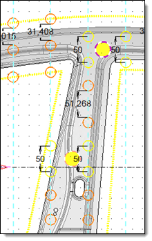
The holes are distributed with priority given to the parts to be cooled and avoided. And then in each intermediate portion, they are distributed taking into account the minimum distance between holes.


The Baffle line points are created with a constraint coincidence with the distribution profiles.

  • Fixities on points: A fixity is added to the baffle line points. They are locked. It is possible to modify them by removing the fixity.