The Main view command allows a set which has
been previously defined to be projected fast with the command Set.
Creation stages:
Select the command View
> Main view... from the drop-down menu.
Select the set to project.
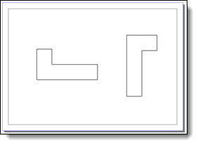
Position the view.
Main
view:
|
Select
the set
here. If no set has been defined previously, you will be asked
this on launching the command. It is also possible to define a
new set by clicking the "+", The document to project
must be opened. |
|
The cameras proposed during
creation of the projection correspond to the 3D file cameras.
The "Associative" cell
therefore allows the associativity of the cameras to be retained
between documents. Example: if the definition parameters of
a camera are modified in the 3D document and the latter is
used in associative mode in the draft, the orientation of
the 2D view will then be updated.

|
A
conical view has some limitations. It can only be cropped
or used by a detail view (Cross section view, interrupted
view, ...) are not allowed. Also, it is not possible to
dimension it. |
|
This option
allows to choose the cameras defined in the source document
of the occurrence. It is useful when you want to make
the drafting of one part only.
It is checked
by default when the view is selected, if the Project
joined parts definition option is activated in
the set.

|
Front camera in the
assembly. |
|
|
Front camera in the
occurrence of
families. |
Result
in the drafting document :
- If the option
is unchecked
(default):
the part is displayed using the front camera
of assembly.
- If the option
is checked: the part is displayed
using the front camera defined in the generic
document of the family instance.
|
|
|
|
Select
the view style to use
here: normal view style (default style) or a customized view style. |
The description of the Scale
, Title, Lines,
Points, Render
mode, Threading, Axes, Hatching
and Detailing option is available
here.
|
Coordinates
: The grid setting allows to sleek
the detailing elements to position. The coordinates can
be cartesian (following X and Y) or polar (radial and
angular steps). Enter values Magnetization:
The magnetization is a hook factor
regarding the entered step. If the step is 10mm and the
magnetization is 2, detailing elements and dimensions
of the view can be moved every 5 mm. If the step is 10mm
and the magnetization is 10, detailing elements and dimensions
of the view can be moved every mm. |
|
This option allows
you to automatically remove line corresponding to the small geometries
(that represents few pixels only) in order to save time during
the projection.
It allows to remove parts of an assembly but also small geometries
created by an operation.
Inherited
from style: The setting
is defined in the view style among the value described
below. None: No
removal of small geometries. Model size: Removal
of small geometries which size of the enclosing box is
lower than the size defined in the Value field. Paper size:
Removal of small geometries
which size of the enclosing box in the drafting document
is lower than the size defined in the Value field. Global percentage: The
computing of the percentage of the geometry enclosing
box compared to the enclosing box of all the shapes. Then,
the geometries which size are lower than the size defined
in the Value field
are removed. Shape percentage:The computing of the percentage
of the geometry enclosing box compared to the enclosing
box of its shape. Then, the geometries which size are
lower than the size defined in the Value field are removed. |
|
Allows you to rotate
the view this the entered angle. |
|
This option allows
to calculate the dimensions of the view via Parasolid,
regardless of the projection mode (fast
or exact). This automatically provides exact dimensions that
do not depend on the model document faceting.
By default, this option is cleared because it can cause software
performance issues. |
|
Automatic:
the view reference point is created automatically. Manual:
The view reference point is defined manually by selecting
a point in the 3d document. Definition
occurrence: In the case of an assembly with instance
families, this option allows to recovered the reference
frame in the occurrence of instance families. |

|
On creation / editing of a main view, you
have the possibility of modifying its orientation
using the keypad proposed by default in the center of the
view. You can change this hooking point by selecting the keypad
then sliding it onto another hooking point (points proposed
in red). It is also possible to change the view's orientation
by dragging with the middle button of the mouse Snap
camera). After validation of the main
view, the creation of an auxiliary
view is automatically proposed. If no set
has been defined previously, you will be asked this on launching
the command. |
Modifications:
Using the right button on an existing main view allows:
To create its auxiliary
views.
To edit the view in order to modify the above options.
To edit the set
in order to change set.
To open the projected document.
To hide the view.
To delete the view.
To rename the view.