This command helps user during component positioning in the assembly.
Creation stages / Use:
This command automatically appears when dragging a component with an associated assistant document.
-
Select wizard type in combo box. For example, for a screw, there are several (Buried head, on top head, ...).
-
The Automatic wizard choice box allows to use a wizard rule.
-
Dragged family is displayed in the combo box.
-
If option Dimensioning explained below is checked, it is possible to check Use best code, that means the most appropriate regarding the dimensioning.
-
Select a code in the combo box.
-
Position the component by selecting a frame. It is created dynamically by moving on a planar surface.
-
Enter an angle to rotate the inserted component around positioning frame Z axis.
-
Enter a gap to add a distance between chosen wizard and positioning frame.
-
Validate by clicking  .
.
Positioning:
|
|
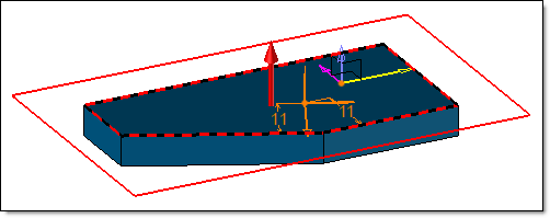
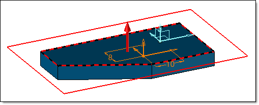
Allows you to define a frame in order to get the same orientation.
|
|
|
Without reference frame, the frame is oriented according to the nearest faces.
|
With a reference frame (in cyan), the frame gets the orientation of the selected frame.
|
Dimensioning: (for screw for example)
This dialog must be checked to be able to use it.
|
|
Dimensioning (minimal diameter and last element to fix) will be calculated by searching the adequate code in the family.
|
|
|
Dimensioning (minimal diameter and last element to fix) will be calculated by selecting manually a component in the search tool.
|
|
|
If this option is checked, dimensioning result will be optimized to find the most adequate component (but calculation will take longer). If this option is unchecked, it is the first in the list responding to criteria which will be used.
|
|
|
Enter the minimal diameter for the inserted component.
|
|
|
Select the last part to fix to be able to know the required component length.
|
Mechanism:
This dialog is only available for inclusion of assemblies with mechanism.
|
|
-
Rigid inclusion: When including an assembly with a mechanism and some configurations, it can be included rigid or not. If Rigid inclusion is checked, the configuration to use can be chosen, but it will be rigid.
-
Use configuration: When several configurations exist in the mechanism, it is possible to select one of them. It will be articulated if it is in the mechanism.
-
Inherit: If including an assembly with a mechanism, its rigid groups, forces and/or joints can be inherited.
|

|
If the mechanism is included as rigid, it is possible to articulate it by using the Articulate contextual command. When it is included articulate, the equivalent contextual command is Make rigid.
|
|
Advanced options:
| |
This option allows to authorize the substitution (replacing) of the extruded bar when the assembly document is included into another assembly.
When it is not checked, the extruded bar will be greyed in the substitution dialog box.
See the sub-component substitution command for more details.
|
Modifications / Additional information:
Modification are made to the component by the popup menu.
