icon or select
Tools > Fibers...
from the drop-down menu.
icon or select
Tools > Fibers...
from the drop-down menu.
|
Fibers |
This command defines the directions of the fibers in anisotropic materials, i.e. their properties are not the same in all directions.
These fiber directions can be used for the texture directions, for hatching orientation, for calculating finished items, etc.
Creation stages / Use:
Click the icon or select
Tools > Fibers...
from the drop-down menu.
Manual:
|
The user selects the fiber directions. The dimensions of the part do not influence the orientation of the fibers, nor the material.
|
Automatic:
|
The user selects a shape. The fibers will be oriented according to the largest dimension of the shape.
|
Managed by material:
|
If the material is isotropic, the fibers are oriented along the largest dimension of the shape, otherwise they are oriented along a fixed direction:
|
Not managed:
|
No fiber management. |
|
To manage the mode of calculation of the fibers in a model, it will be enough to choose the desired mode (Manual, Automatic or Material) and fill in the fields with the value "not specified". When creating the first shape (extruded, block, enclosing block, constrained block), if the fibers are managed but not specified, TopSolid will automatically assign the values: · Manual: o Origin: origin of the largest linear edge. o First direction: the largest linear edge. o Second direction: linear edge adjacent to the first one. If there is no linear edge, nothing is done. In this mode, the fiber operation will be placed just after the operation that created the first shape, in order to avoid invalidities if the edge or the origin were to disappear.
· Automatic: o Shape: the shape that was just created.
· Managed by material: o Frame: frame giving the direction of the fibers. A frame is automatically created, based on the largest linear edge, its origin and the adjacent edge. It will orient the fibers if the material is anisotropic o Shape: the shape that was just created. |
Available options:
The Create frame option allows to create the frame according to the fiber directions (origin and axes along the 3 given directions).
This frame is created in the Analysis stage by default, but it can be moved in the Design stage thanks to the Others > Change Stage... contextual command on the Fiber Management operation.
Additional Information:
By default, the material orientation is applied according to the absolute frame.
The 3 given directions correspond with the 3 axes X,Y and Z of the new frame that will be used.
|
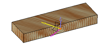
Default fibers orientation according to the absolute frame. |
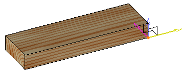
|
Fibers orientation
defined according to the part edges. |
 button.