
Movement on Point
|
Movement on Point |
Icon Access: 
Location: Annex \ Movement on Point...
Development:

Since the 7.7 version, this function is replaced by the virtual jog which allows to make manual movements and also lots of other simple operations (dwell, direct block, Pp remark, .....)
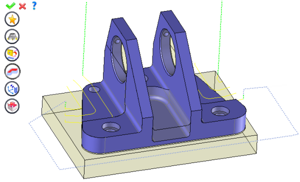
Manually define a linear trajectory between several points, for example, to contour an obstacle, define a linking movement between two operations or complete a type of mouse surfacing.
Example of classic movements on top of part during interoperation |
|
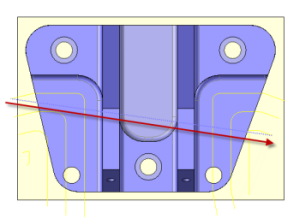
Example of manual add of movement on point during side pass interoperation. |
|
The movement on point is a MANUAL function. The operator has full control over the trajectory and its quality. It has the same characteristics as a classic milling operation and is automatically inserted at the end of the range when it is created. It can then be moved to the range using the mouse.
From the "Annex" menu, select Movement on Point.
An icon bar appears to the left of the screen.
To define the various passage points, click the geometry button  and to select points. The cutting conditions are identical for all selected points.
To add additional points, click the  icon. You can also define a specific feed rate or work plane or return to tool change point using this option.
|
Select the tool to use
By default, if the previous operation tool can be used, it is reused for this operation (the name of the tool appears in the graphic area next to
If the previous tool is not suitable or if this is the first operation, you must select a tool to validate the operation (
|
|
Select a "preset"
Instead of modifying n values, this option allows you to restore (or save) values that have already been entered. |
|
Define Cutting Conditions for Operation
Use this icon to modify the cutting conditions of the current operation.
|
|
Define or Add Geometries to Machine
Use this icon to select (or remove) machinable geometries.
|
|
Define ISO File Settings
Use this icon to define which comment to use for the ISO code or to decide which inclined plane matrices to use.
|
|
Define colinear axis
This icon is available only if the current machine has colinear axis.With this icon it will then be possible to choose the axis drives by the operation.We also can choose the Z value of the fix axis. |
|
Define Operation Properties
Use this icon to define whether you would like to update the stock or calculate the result later.
|
|
Confirm
To confirm the current operation, pressing this icon to right-click outside the window and use the "OK" menu
|
|
Cancel
If you wish to cancel the operation, click this icon.
|
|
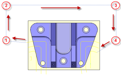
To modify the order of the passage points for a movement on point, move the tops of the geometries to the milling range.
|
|
|
1:Helical Drill D10 L35 SD10 |
||||
|
|
|
[A: 0°; B:0] |
|||
|
|
|
|
|
||
|
|
|
|
|
Multiple Geometries... |
|
|
|
|
|
|
|
Shape 1 Top 1 |
|
|
|
|
|
|
Shape 1 Top 2 |
|
|
|
|
|
|
Shape 1 Top 3 |
|
|
|
|
|
|
Shape 1 Top 4 |

 )
) )
)


 1: Movement on Point
