
Cylinder and Drilling Analysis
|
Cylinder and Drilling Analysis |
Icon Access: 
Location: 2D/3D \ Cylinder and Drilling Analysis
Development:
Search and group available geometries with drillings in a part set in order to mill them by automatically applying the adapted method. The set of features are grouped into two dialog boxes:
|
The dialog box "Analysis of drillings and cylinders" allows to configure the analysis.
The configuration options for the analysis can be set by default in the machining options.
|
||||
|
The "Sorted Drillings" dialog box groups the set of drillings on the part found by TopSolid'Cam.
|
||||
|
The "2D View" dialog box allows you to see the detected stacks and modify the correspondences between the cylinder stacks and the milling methods.
|
||||
|
The dialog box "Execute Methods" allows to configure the execution of methods.
|
A results window that specifies all sorted drillings is displayed.
 By default all the part is analysed but it is possible to define an area to limit the analysis.
- To create this area just use the fonction [ Equipment / Part / Part analysis limitation].
- To limit the analyse to this area it is necessary to select it in the list  below.
|
|||||||||||||||||||||||||||||||||||||||||||||||||||||||||||||||||||||||||||||||||||||||||||||||||||||||||||||||||||||||||||||||||||||||||||||||||||||||||||||||||
TopSolid'Cam studies the selected part in order to retrieve the geometric characteristics that define the holes to make such as the cylinder diameter, the cylinder stack, etc.
Following this analysis, four cases are available:
|
TopSolid has found only one method for completing the geometrical form.
|
|
TopSolid has found several methods to achieve the geometric shape. Select the one to use using the
|
|
A method has been selected from the list to complete the geometric shape found by TopSolid'Cam.
|
|
No method has been found by TopSolid'Cam for the geometric form.
|
You will therefore be able to machine (by checking the box  ) only the groups
  and
and  .
.
Other commands are available:
|
Merges two operations into the same stack (often, these two operations have been manually separated using the Separate function).
|
||||||||||||||||
|
If several milling methods correspond to the cylinder stack, this icon allows you to validate the first method directly.
|
||||||||||||||||
|
Allows access to the drill hole analysis configuration.
The WCS, the diameter, the depth... It is also possible to automatically reduce the drilling tree.
"Check collisions": when the option is enabled collision detection is forced for all drilling operations. "Apply depth from top element": when the option is activated the depth of each hole with the "full definition" type is automatically applied to the top of the stack.
|
||||||||||||||||
|
Selects the milling method to associate to a cylinder stack. This icon also allows you to change the method by deleted certain operations, for exemple, a centering or front hole.
|
Filters
Having filters allows you to eliminate some results in order to best view the missing information to be entered:
|
Eliminates all cylinders that have been completely milled from the analysis results. |
|
|
Eliminates all cylinders that have been partially milled from the analysis results.
|
|
|
Eliminates all stacks that have been partially milled from the analysis results.
In the list of holes, a hole considered as partly machined is shown in blue with the info "drilling (partly machined)" |
|
|
Eliminates all stacks that have been completely milled from the analysis results.
In the list of holes, a hole that is considered to be completely machined is shown in blue with the info "drilling (fully machined)" |
|
|
Eliminates all stacks which have no angular solution. |
|
|
Eliminates all stacks with one compatible milling method from the analysis results.
|
|
|
Eliminates all stacks with several compatible milling methods and for which a method is already selected from the analysis results.
|
|
|
Eliminates all stacks with several compatible milling methods and for which a method has not been selected from the analysis results.
|
|
|
Eliminates all stacks with no milling method from the analysis results. |
|
|
When holes have been manually hidden this button allows you to show them again. To distinguish them in the list the holes that have been hidden appear in gray.
|
Matches
When the cylinder stack on the part does not allow TopSolid to match the milling method, you can delete the matching criteria.
right-click the operation. Then in the geometry topic, select one of the following four options:
|
Include chamfers Takes into account the chamfers in the method selection.
|
|
Omit Chamfers Does not take into account the chamfers in the method selection.
|
|
Include bottoms Takes into account the drilling bottom in the method selection.
|
|
Omit Bottoms Does not take into account the drilling bottom in the method selection.
|
In the example below, the drilling analysis cannot match the "Drilling + Spot Facing" method due to the presence of a lead in chamfer.
By using the option Omit Chamfers for analyzing this operation, the correspondance is done.
|
|
|
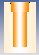
No method found due to lead in chamfer |
|
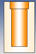
A method can now be found because the chamfer is no longer taken into account |
|
Omit Chamfers |
|
Drilling Merge and Separation
A cylinder stack can be made up of several successive methods.
If desired, you can separate them manually in order to delete part of the stack and apply different methods.
The reverse operation consists of merging these stacks.
|
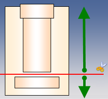
Separate In the 2D View box, this icon allows to position the red cursor on a cylinder in order to split the stack in two.
|
||
|
Merge In the "Sorted Drillings" box, this button allows you to merge two operations from the same stack.
|
The example below shows a stack of three cylinders.
No method (for our example) is available to complete this stacking.
However, a "Drilling + Spot Facing" method and a "Back Spot Facing" method are available.
By separating the stack you can use these two methods.
|
|
|
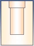
No method found automatically because the three cylinder stack does not match a method |
|
A method can now be found because this stack has been cut into two |
|
separation of stack into two. |
|
|
Double-clicking the arrow going across a drilling allows you to reverse the milling direction (through drilling).
|


 icon or by clicking the question mark.


 This option is only visible if the search for partial cylinders was requested in the hole analysis configuration.


 it is possible to keep all the separations made by checking the box apply cuts.

 Right-clicking an operation or operation group in the "Sorted Drillings" window allows you to view them on the part and right-clicking a part cylinder allows you to find it in the "Sorted Drillings" window operations list.