3D Finishing
|
3D Finishing |
Icon Access: 
Location: 2D/3D\3D Finishing
Development:
Automatically complete a limited volume finish of a shape part using a hemispherical or ring mill.
This finishing can be followed by 3D remilling in areas that cannot be accessed by the tool used for 3D finishing.

Finishing operations depend directly on the faceted model of the finished part, by taking into account areas that cannot be accessed by the tool.
Trajectories are automatically calculated over the entire machinable area of the part. This milling area can be redefined by the user in order to trim trajectories.
From the 2D/3D menu or using the mouse (by selecting or not selecting a face with the right mouse button), select the "Finishing..." menu.
A toolbar appears on the left of the screen, along with a label in the graphic area.
You can then modify values by
By selecting the value to modify in the label. The label is the table shown in the image in the top right corner. All label values are fields available from one of the icons in the left section. These values are placed on the label for quicker access.
By selecting the values in the graphic area or by pulling the arrows. As with the values of the labels, these fields are present in one of the left section icons. These values are placed in the graphic area for quicker access.
By opening one of the left section icons.
|
Select Favorite
Instead of modifying n values, this option allows you to restore (or save) values that have already been entered.
|
|
Select the tool to use
By default, if the previous operation tool can be used, it is reused for this operation (the name of the tool appears in the graphic area next to
If the previous tool is not suitable or if this is the first operation, you must select a tool to validate the operation (
|
|
Define Cutting Conditions for Operation
Use this icon to modify the cutting conditions of the current operation.
|
|
Define or Add Geometries to Machine
Use this icon to select (or remove) machinable geometries. This geometry is automatically added, by first selecting the geometry and right-clicking "End Milling". By doing this you won't need to access to this icon.
Define Milling Boundaries
You can also apply trims (XYZ or contour) to the current operation.
|
|
Define all milling settings
Each milling has specific settings. Use this icon to access all settings (such as stocks to leave, altitudes, plunge modes, milling modes, etc.)
|
|
Define ISO File Settings
Use this icon to define which comment to use for the ISO code or to decide which inclined plane matrices to use.
|
|
Define colinear axis
This icon is available only if the current machine has colinear axis.With this icon it will then be possible to choose the axis drives by the operation.We also can choose the Z value of the fix axis.
|
|
Allow us to add one or more axis on the current machining
With this icon it is possible for example to make radial, axial or tilt the operation.
|
|
Define Operation Properties
Use this icon to define whether you would like to update the stock or calculate the result later.
|
|
Confirm
To confirm the current operation, pressing this icon to right-click outside the window and use the "OK" menu
|
|
Cancel
If you wish to cancel the operation, click this icon.
|
|
Preview
Display or hide the machining area. When this is hidden, this area is not calculated, and response times improve.
|
|
Show Label
Allows you to display or hide the graphic area label.
|
|
Editing Update
Each time a setting is changed (such as the axial depth), all calculations for updating the hatching area and the trajectory are triggered. The setting change may take a few moments. In several cases, settings must be modified before updating the calculations. For this, press this icon. In the case, the hatching area and trajectory (for example) are not recalculated before pressing this icon again.
|
The parallel plane milling mode allows you to automate the creation of paths using the same principle as the old machines to be copied. The tool follows the digital shape to complete like a spindle follows a wood model, the movements of this spindle being locked on an axis such that it can only move perpendicularly along the XY plane. |
|
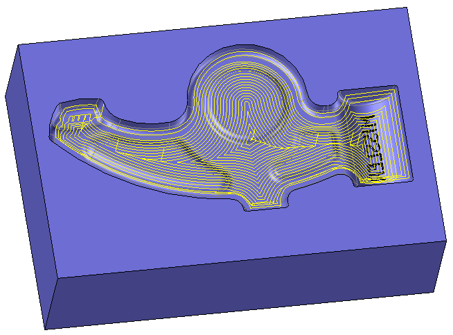
Particularly for part finishing, this type of operation consists of automatically milling a part made up of a set of faces by completing a series of concentric contourings and varying the space between each face in order to maintain the height of the scallop no matter the curved surface of the part using a contour provided by the operator.
If a gap is applied, the step over must be less than (tool radius - gap) / 3. |
|
This technique allows you to use the best cutting conditions for the greatest productivity. The cutting speed required is followed because the tool rarely mills to the center. In addition, the feed rate remains constant, and the tool only descends when the Z plane is changed. |
|
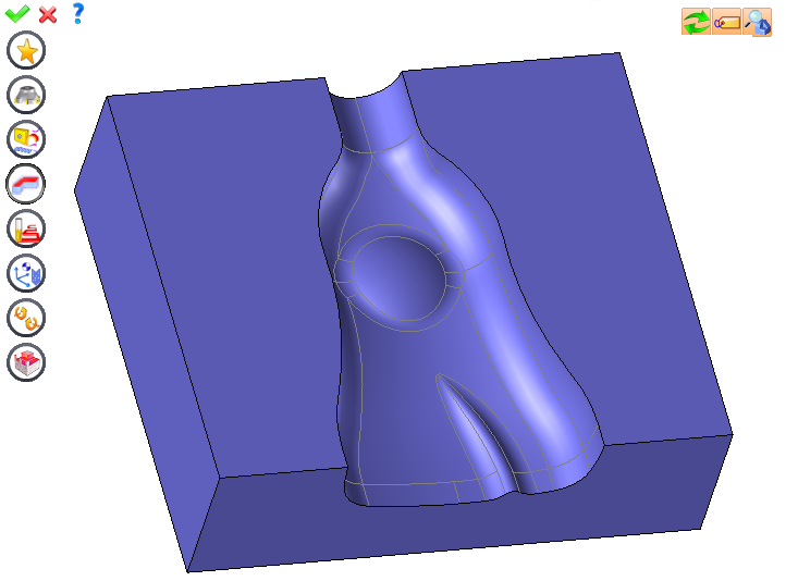
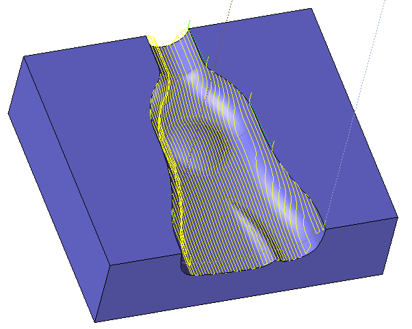
The faces that make up the model to mill are cut into radial planes containing the segment defined by the user in the guide curve. These planes are regularly spaced at a radial pitch.
Milling is completed longitudinally in the direction of the revolution axis. The step over movement can be a square cycle or classic zigzag, staying in contact with the part or not. |
|
This technique allows you to mill a part to avoid jumps on the trajectory and "esthetic" marks on the part. Spiral milling is then completed. To avoid rapid jumps, the scallop value is decreased to force the tool to redo the areas requiring rapid jumps. You must select a starting curve, an ending curve (or a point), and their points of origin. These points must be aligned so that the pass spirals are best calculated. You can optimize the trajectory so that it is more "fluid" by selecting intermediate curves.
|
|
This feature is specifically for semi-finishing parts. This type of operation consists of automatically milling a part made up of a set of faces by completing a series of concentric contourings projected onto the part.
The user resolves the main part geometry problems, such as:
|
|
 Click the different areas in the image below
Type of Machining |
|
Computing Tolerance |
|
Stock to leave on floor |
|
Stock to leave on side |
|
Step overs |
|
Scallop Heights |
|
Sweeping Angle |
|
|
|
Visibility management when editing the operation: click on the icons below
Machine visibility |
WCS visibility |
Tool visibility |
Collision visibility |
Stock and finish visibility |
Tool paths visibility |
|
|
|
|
|
|
|
|


 )
) )
)

 For a 3D finishing, bounding curves must be on the part.


 Constant Pitch
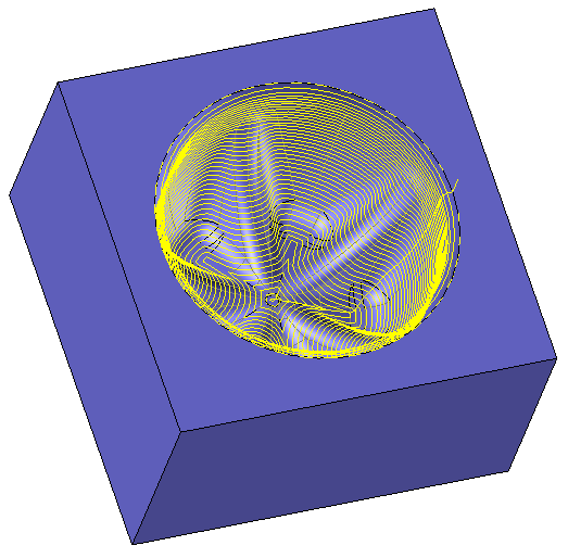
 Constant Z
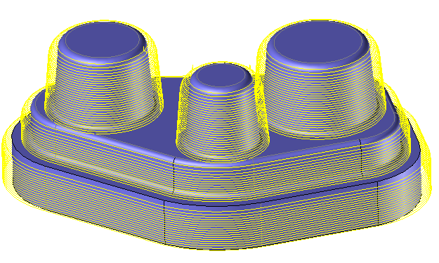
 Projection
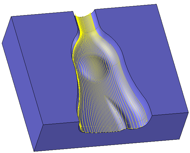
 Morphing
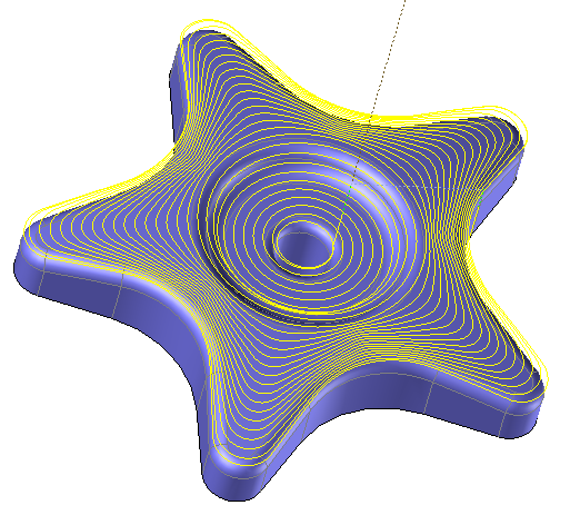
 Projected Spiral