Fillet
|
Fillet |
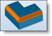
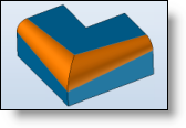
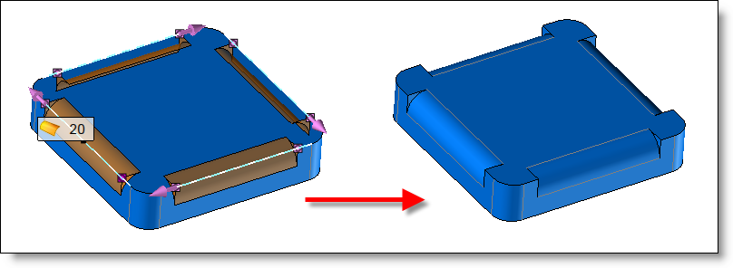
This command allows you to create fillets on shapes.
Creation Stages / Use:
Click the
icon or select Shape >
Fillet.... from the drop-down menu (or Modeling
> Local Shapes > Fillet in the assembly document).
Choose the fillets building mode: Identical or different radii (see details in the available options)
Enter the fillet value.
Select edges and/or faces on which to apply the fillet with the entered value.
Available Options:
Radii:
|
Identical : in this mode, all of the edges/faces selected will use the same radius value. If the radius value is modified while in use, then the edges/faces already selected (and those selected thereafter) will use this same new radius.
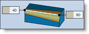
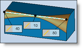
Different : in this mode, it is possible to assign different radius values to the edges/faces selected. Thus, when you change the value of the radius, the edges/faces already selected will still use the value of the radius which was entered when they were selected. The new edges/faces selected will use the new value. This mode also allows you to create fillets of which the radius is variable (described in detail below) |
Edges:
|
The edges/faces selected will be appear in this list To delete elements from this list, it is possible to select them again in the graphic area or to select them from the list and use the "Delete" key on your keyboard. If the selection contains multiple invalidities, the contextual command Delete Invalid Selections allows to remove them quickly.
By checking Shape edges, all edges of the shape are selected.
If the Radii option is set on "different", then two new columns are displayed in this list:
To modify the fillet type on an edge/face, click the corresponding cell and select the desired type from the drop-down list by using the contextual menu.
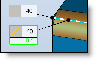
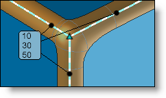
For variable type fillets, it is therefore possible to modify the start and end values of the fillet using the labels. To do this, double-click the numeric value on the label.
To add intermediate radius values on a variable fillet, right-click the affected fillet labels and select the "Add Radius" function. A new value point then appears with a label as illustrated below.
|
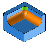
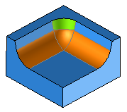
Corners:
|
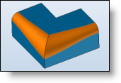
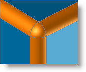
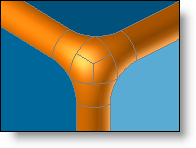
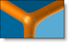
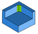
This option allows you to create a "ball corner" at the connection of 3 edges on which a fillet is applied.
You can modify the amount of the roundness along each edge by modifying the offset value corresponding to each edge or by dragging each point along the edge:
|
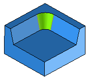
Constraints:
|
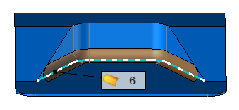
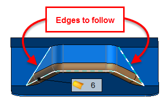
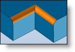
This option allows you to specify the edges to follow. In this case, a variable fillet is created at the fillet's ends.
|
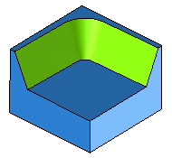
Limits:
|
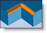
By default, the fillet is applied on the complete selected edges. This option allows to define limits.
|
Overflows:
|
This option allows you to define how to create the fillet when it extends onto neighboring faces. You can define this behavior independently for an extension on smooth edges and on square edges.
An image in the dialog illustrates the principle of the selected option.
|
Overlaps:
|
This option defines how overlapping fillets will be created.
An image in the dialog illustrates the principle of the selected option. |
Advanced Options:
|
Dynamic preview : If this option is checked, then the preview of the fillet is updated dynamically by dragging on an offset point of a ball corner or on a value point of a variable fillet.
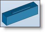
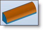
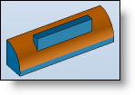
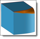
Keep overlapped faces : When this option is checked, TopSolid stores in the memory the topology of the faces which disappeared after creation of the fillet. This keeps you from losing operations that use these faces as references. Below is a shape with a boss operation made on the upper face. The fillet makes this face disappear. Here the behavior difference is observed.
Repair self-intersecting : This option allows you to automatically repair the auto-intersection area of a fillet. This option allows in some cases certain fillets to be able to be created despite the fact that the surface of the fillet self-intersects.
Vertex blending : This option allows you to round off corners between two consecutive fillets.
Variable fillet on edge : This option allows to smooth the junction between 2 edges.
Tight curvature of adjacent faces: "Tight curvature" means here that the curvature radius of the face is smaller than the fillet radius. This option allows to modify the construction method of the fillet on lateral faces that have a curvature radius smaller than the fillet radius. it is possible to choose among 3 types of situation:
|
Modifications:
Double-click the fillet to display and modify the values of the radii.
Additional information: