Boolean
|
|
Boolean |
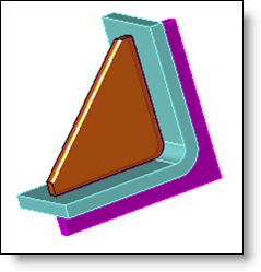
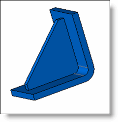
This function performs Boolean operations among several shapes: union, subtraction, and intersection.
Creation Stages / Use:
Click the  icon or select Shape> Boolean... from the drop-down menu (or Modeling > Local Shapes > Boolean in the assembly document).
Select the shape to modify.
Select the type of Boolean operation to perform on this shape:
|
|
|
|
|
|
|
|
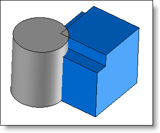
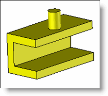
Original shapes |
|
|
|
|
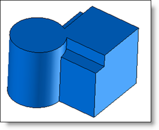
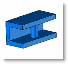
Union: |
|
|
|
Union of the 2 shapes |
|
|
|
|
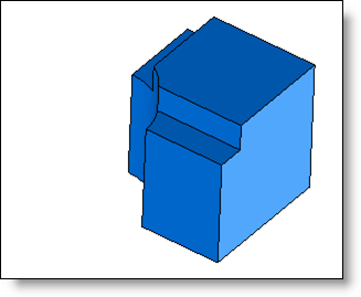
Subtraction: |
|
|
|
Substraction of the cylinder |
|
|
|
|
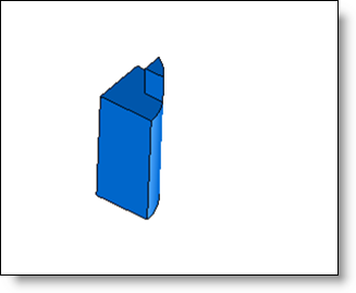
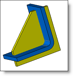
Intersection: |
|
|
|
Intersection of the 2 shapes |
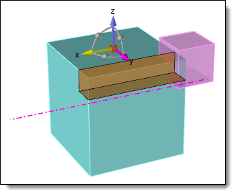
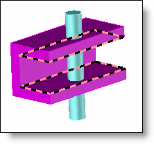
Select tool shapes for boolean operation
Validate by clicking  .
.
Available Options:
Hide:
|
|
This option allows to hide the selected elements (it can helps to the selection of other shapes that could be hidden by the shapes already selected). |
Clearance:
|
|
When you choose the subtraction mode, you can define a clearance value that will be applied on all the faces of the tool shape. In such case, the tool shape is parallelized with the clearance value in all the direction and this shape is subtracted to the shape to modify.
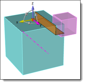
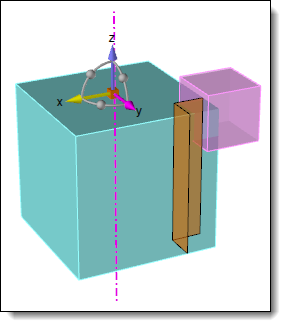
The Direction to through option allows you to extend the tool according to the given direction:
|
Fillets:
|
|
This option allows you to add, on final result, a fillet on every intersection edges between the shape and tools. |
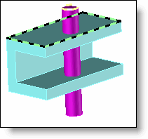
Local operation:
|
|
This option allows you to use only some shape or tool areas.
|
||||||||||||||||||
Advanced options:
|
|
Check this option to check faces. If this option is not checked, calculation will be faster, but can generated some invalidities. The Optimize coincidences option allows to better resolve tangency (coincidence) problems between faces of the part to modify and the tool. A tolerance value can be given, it will influence the search for the tangent faces to optimize. |