Analyze normal
|
|
Analyze normal |
This command allows to display, through a color code, the angle of the normal according to a given direction. This is useful for example to display the counter-drafts on a part.
Creation stages / Use:
Click on the icon or choose the command Analysis > Analyze normal... from the drop down menu.
Select the shapes to analyze.
Choose the reference direction. The angles will be measured according to this direction.
Select an angle type:
Normal-direction: Allows to analyze the geometry angle which will be calculated between the selected direction and a normal axis.
Normal-plane: Allows to analyze the geometry angle which will be calculated between the selected direction and the plane normal to this direction. The result is the complementary of the angle type Normal-direction.
Draft: Allows to use negative angle values. This can be useful to visualize the counter-drafts on a part. The color scale has 3 colors. The Vertical faces allows to sleek the colors scale.
Validate with to visualize the result.
|
|
Click the |
Available Options:
Hide:
|
|
This option allows to hide the selected elements (it can helps to the selection of other shapes that could be hidden by the shapes already selected). |
Color palette:
|
|
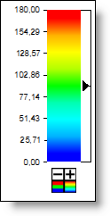
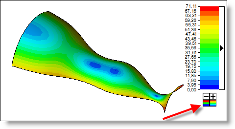
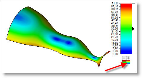
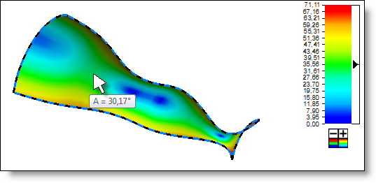
The color palette allows to modify the scale color to adapt it to the part geometry and so be able to visualize more easily the small angle variations. The "-" or "+" under the color range allow to increase or reduce the curvature values range on the graduations. By clicking on the small color square under the color palette, the color range can be either continuous or discrete.
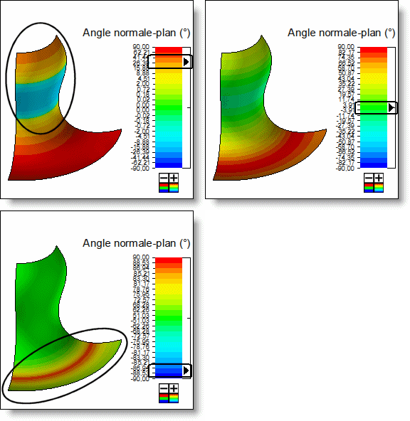
The small vertical slider on the right of the color scale allows to modify the distribution of the angular values onto the color scale. Pull up the slider allows to get a better reading for small angles. Pull down the slider to visualize more easily the high value angle. On the example bellow, the reference direction is vertical.
In Normal-Plane or Draft mode, additional buttons appear bellow the color palette: They allows to activate/deactivate the visualization of faces with a negative, null or positive draft angle.
|
|
|
To get the angle on a given point, you just need to move the mouse above this point on the part
|
|
|
Double click on the highest value of the scale to change it. It allows to increase the accuracy and to not display unused values. If the shape to analyze has no counter-drafts, the scale may be between 0 and 90°. |

 icon in the workspace area to leave the analysis.