Creation of a font for a wire text
|
|
Creation of a font for a wire text |
When using the wire text command, a font is required to draw the text.
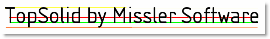
Some reminders regarding font terms:
|
|
|
|
Yellow line |
Top line: It is the upper line of the enclosing characters box. |
|
Red line |
Center line: It is the middle line of the enclosing characters box. It can change regarding the character type (with or without downstroke, uppercase, ...) |
|
Green line |
Base line: it is the line on which is written characters. |
|
Orange line |
Bottom line: It is the lower line of the enclosing characters box. |
Steps to create a new wire text font:
Create a new 2D Model document.
Create a parameter allowing to drive the character height. (you can have several parameters). They can be used as drivers, to define a catalog, ...
Create as many sketches as there are characters in the font. An uppercase character is not the same as a lowercase. You need 2 sketches for a character.
Each sketch has the name of the character it defines.
|
|
|
Use the Provide function command and select the Wire text function in the drop-down list to allow the Pdm to find it and propose it in a list all available wire text.
Create a family with the contextual command from the 2D model document tab.
This 2 Model document can be defined as a virtual document.
In the family, fill codes or drivers. Defined codes and drivers will automatically appear in the dialog during the creation of a wire text in a sketch.
Don't forget to save and check in these documents.
|
|
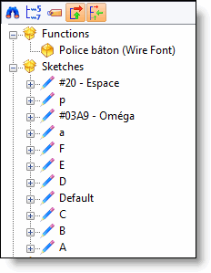
In the entities tree of the 2D Model document, each character as its own sketch at its name. The wire text function has been provided. |
|
|
|