Modify grid
|
|
Modify grid |
This command allows the appearance of the entry grid and entry mode of the coordinates to be modified.
Modification steps:
Click the  icon or select the 2D sketch or 3D sketch > Modify grid... command from the drop-down menu. In a Draft document, select the Sketch > Modify grid... command from the drop-down menu.
Choose the grid type from the 3 modes proposed:
|
None |
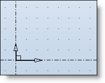
Points type grid (Cartesian) |
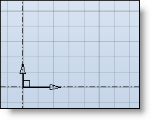
Lines type grid (Cartesian) |
|
The grid is not displayed the cursor is then free of all movement. |
|
|
Choose the coordinate entry mode:
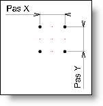
In Cartesian mode the points are entered by indicating the X and Y coordinates
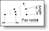
In Polar mode the points are entered by indicating a radius and an angle. This mode is then used in all the sketch creation commands.
Depending on the coordinate entry mode, set the different pitches of your grid.
The Magnetization option corresponds to the number of intervals between two grid points.
E.g.: On a grid with a pitch of 10mm in X and in Y and a magnetization of 5, it will be possible to position every 2mm in X and in Y.
|
Adjustment of a grid in Cartesian mode |
Adjustment of a grid in polar mode |
|
|
|
|
The small red points represent the magnetic grid, in these examples magnetization has been set at 2. |
|
|
|
The grid has an auto-adaptive pitch, i.e. depending on the zoom, the pitch is multiplied or divided by a factor of 2, 5, 10,... |