Coincidence relation
|
|
Coincidence relation |
This relation allows an element to be positioned on another.
Creation Stages / Use:
Click the  icon or select the 2D sketch > Constraints > Relations > Coincidence.. command from the drop-down menu. In a Draft document, select the Sketch > Constraints > Relations > Coincidence... command from the drop-down menu.
Select the two elements to be made to coincide: the two elements are moved and the Coincidence symbol is displayed between the two elements.
|
Elements selected |
Result |
|
Two points |
The points are superposed. |
|
A point and a line, an arc, a circle or an edge. |
The point is placed on the element or in its extension. |
|
Two lines |
The lines are placed collinearly. |
|
|
To delete the Coincidence relation, you must select the Coincidence symbol then press the Del key on your keyboard and choose the command Delete from the popup menu displayed by right-clicking. |
Modifications / Additional information:
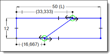
When a coincidence constraint has been defined between a point and a segment, the Fix ratio contextual command allows you to define the location of point proportionally to the segment dimension.
In this case, the circle used for the coincidence constraint is replaced by a double arrow as shown below:
|
|
|
|
|
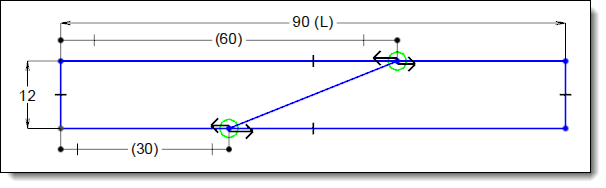
In the example above, the ratios of the coincidence constraints have been fixed to 1/3 (at the bottom) and 2/3 (at the top) of the segment lengths. |
|
Then, these ratios are kept during the modification of the rectangle length. |
The Unfix ratio contextual command allows you to delete the ratio constraint and get back to an simple coincidence constraint.