Welding symbol
|
Welding symbol |
This command allows a welding symbol to be created in your draft document.
Creation stages:
Click the icon or select Detailing > Welding Symbol...
from the drop-down menu.
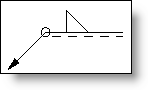
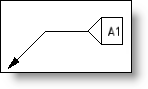
Select a geometry.
Select the welding symbol style to use: Normal Style (default) or a customized style.
Position the symbol.
Validate
Available Options:
Projected welding symbol:
This option allows to automatically recognize welding types used in the assembly and to select the corresponding symbol. When this option is activated, upper and lower informations are not available.
Wweld Information:
|
- The symbol is placed beside the continuous line or the reference line if the outside face of the weld is on the frame line side. This is the default mode. - The symbol is placed beside the interrupted line if the outer face of the weld is on the opposite side to the frame line. For that, you must activate this cell.
- This cell allows stating that the weld is of staggered type. - To free this option, the upper and lower weld symbols must be identical. |
Upper/lower informations:
|
These options are not available if the Projected welding symbol option is checked.
Select the symbol corresponding to your weld in this menu (V weld, angle weld, point weld, etc.). Depending on the symbol selected, additional information could be added (height, width, penetration depth, etc.).
In this menu select the shape of the surface of your weld.
If necessary, you can add an additional symbol.
If necessary, you can enter an finish character.
|
Welding process:
|
These options are not available if the projected welding symbol is checked.
|
Format:
|
Displays the name and size of the font used. Use the Font cell to activate the button and then modify the settings (font, style, size, effects, etc.). The button displays changes.
Select the color of the text by clicking the button. The pipet allows to select an existing color, the black cross to remove the chosen color.
Assign a layer to the element. The layer can be created on the fly by clicking the "+".
|
Advanced options:
|
Extremities: Allows to modify dimension extremities: leader style, size, ... |
Modifications:
To modify an existing welding symbol, simply right-click to select it and select the Edit command.