With this document we can define a new sequence of chip breaker.
Putting this document in a user library allows us to access to this document in all the projects.
|
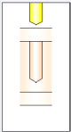
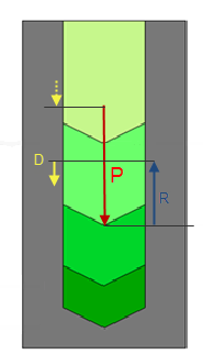
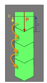
In this document we are going to define the steps to realize a set of drillings.
Each drilling with a depth (P)can contain an ascent (R)a descent (D) a dwell, or a rotation direction.
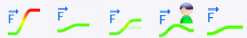
A first set of icon allows to define the action to realize.
| Ascent Descent Machining Dwell Rotation direction Coolant |
We must then select between one of those 6 actions and define its parameters.
To validate and create an action click on the icon  a color graph allows to simulate the action.
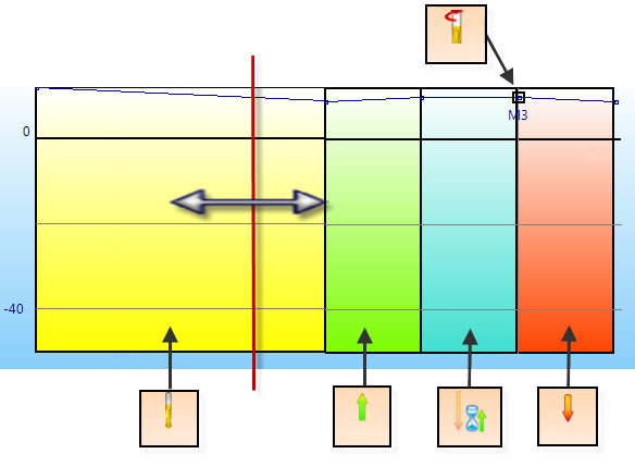
The following example shows a sequence of 5 actions: "Machining", "Ascent", "Dwell", "Rotation direction" and "Descent".
Description of the 6 actions:
 |
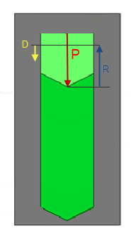
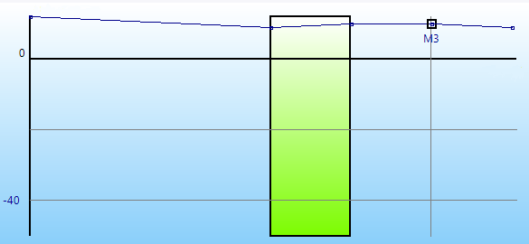
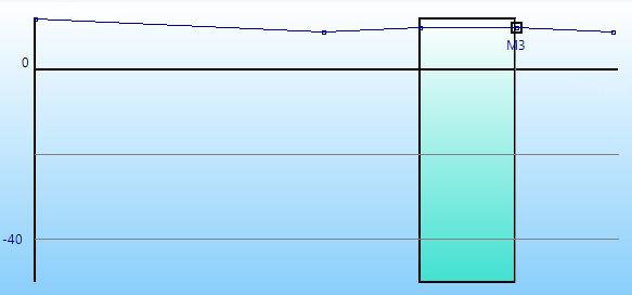
Machining :
This option allows to create a drilling with a customized depth.
|
||||||||
 |
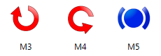
The retract :
This action allows to realize an ascent in Z.
|
||||||||
 |
Dwell :
This option allows to create a delay.
|
||||||||
 |
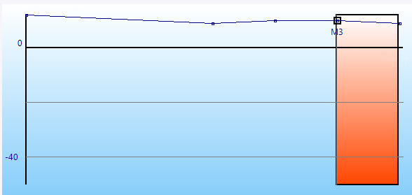
Rotation direction :
This action allows a rotation direction change or a spindle stop.
When the box is checked it is possible to define a factor to apply on the initial spindle rate defined in the cutting conditions of the operation.
When the box is unchecked it is possible to define a custom spindle rate.
|
||||||||
 |
Plunge :
This action allows to realize a plunge in Z.
|
||||||||
 |
The coolant :
It allows to activate or not the coolant with the desired mode.At the end 5 coolant modes can be use.The coolant pressure unit is the bar.
|
The "Loop" option allows to repeat a sequence from a step to another one to have the drilling fully machined.
|
|
 |
 |
|
It allows to add an action at the end of the sequence. Select the type of action, set the parameters and click on the icon to add it. |
||||||
|
It allows to add an action in a sequence. Click in the board of the actions to select the position, define the type of action and the parameters then to click the icon. |
||||||
|
It allows to delete a step. Click in the board of the actions to select the action to be deleted, then to click the icon. |
||||||
|
It allows to modify a step. Click in the board of the actions to select the action to be modified, then to click the icon. |
||||||
|
Configuration
|


 The color code in the graph is yellow
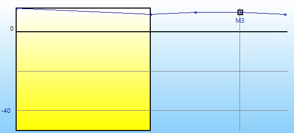


 Spindle rate factor
 Spindle rate factor
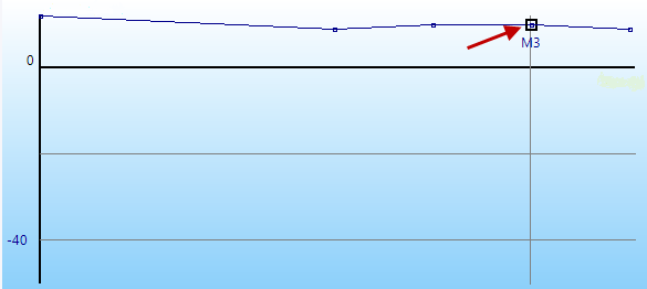


 .
.