|
Import TopSolid v6 - Assembly document |
All TopSolid v6 document defined as assembly can be translated as a TopSolid 7 assembly document whether it is designed with in place parts or by mounting. Each part is converted as part document, each sub-assembly as assembly document.The option Translate assembly structure must be checked.
Translated attributes are:
The color
The transparency
The layer
The visibility (show, hide)
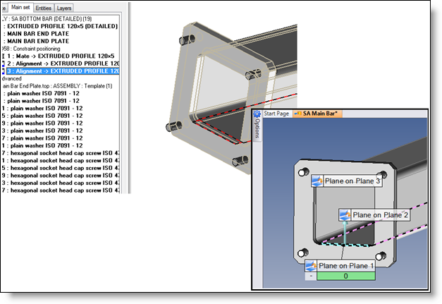
Positioning constraints:
The positioning constraints are also translated as TopSolid 7 positioning constraints. The option Import positioning constraints must be checked. The constraints must be applied on the shape geometries (surface, edge or vertex) or on frames (axes, origin point), but not on geometries like curves.
The concerned geometry must exist in the translated document. For example, if an axis on axis constraint is created by using edges and if these edges are deleted but a future operation (for example a chamfer), the constraint is not translated because the edge doesn't exist in the translated document.
The constraints equivalence list:
|
TopSolid v6 Constraints |
TopSolid 7 Constraints |
|
Contact |
Plane on plane Surface on surface |
|
Alignment |
Axis on axis Plane on plane |
|
Orientation |
Orientation |
|
Point on point |
Point on point |
|
Axis on axis |
Axis on axis |
|
Plane on plane |
Plane on plane |
|
Point on axis |
Point on axis |
|
Point on plane |
Point on plane |
|
Axis on point |
Axis on point |
|
Axis on plane |
Axis on plane |
|
Plane on point |
Plane on point |
|
Plane on axis |
Plane on axis |
|
Frame on frame |
Frame on frame |
|
Surface on axis |
Not managed |
|
Axis on surface |
Not managed |
When constraints are translated, they are hidden. They can be shown by using the Show contextual command from the constraints folder of the entities tree.
|
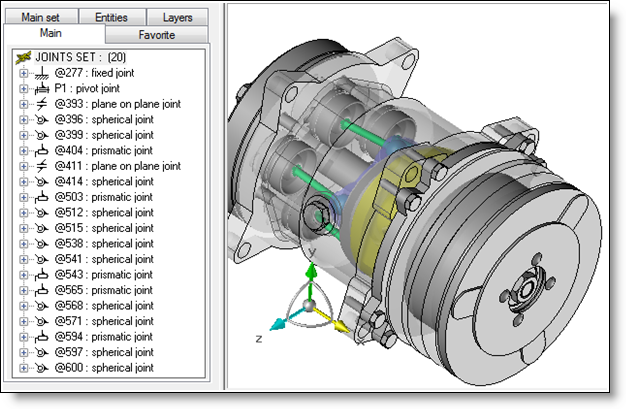
Kinematics:
The TopSolid v6 kinematics can be translated by checking the Import kinematics option.
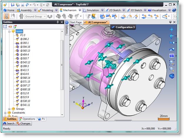
The translation creates the rigid groups and includes into them the different components and then translates the different joints. The created rigid groups and joints are named with the TopSolid v6 names.
All components not included into a TopSolid v6 rigid group are included into the TopSolid 7 ground group. All fixed or welded components are included in the TopSolid 7 ground group.
The constraints equivalence list:
|
TopSolid v6 joints |
TopSolid 7 joints |
|
Ground |
Not managed, Ground rigid group |
|
prismatic |
prismatic |
|
Revolute |
Revolute |
|
Spherical |
Spherical |
|
Cylindrical |
Cylindrical |
|
Point on axis |
Point on axis |
|
Rigid |
Rigid |
|
Planar |
Planar |
|
Axis on plane |
Axis on plane |
|
Point on plane |
Point on plane |
|
Polar |
Slot and pin |
|
Screw |
Screw |
|
Gear |
Gear |
|
Rack |
Rack and pinion |
|
Point on curve |
Plane on profile |
|
Plate cam |
Not managed |
When joints are translated, they are hidden. They can be shown by using the Show contextual command from the joints folder of the entities tree.
 |
 |
Alternative set:
The TopSolid v6 alternative sets are managed as TopSolid 7 representations. All entities of the alternative assembly are transferred in a new representation named with the alternative assembly name.