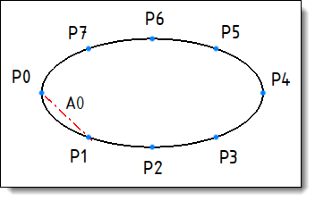
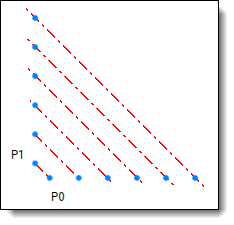
Element to serialize: axis between P0 and P1.
Driver provider: the repetitions of P0 and P1 points.
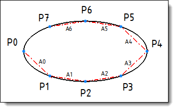
Result of serialization: the new axes are automatically created on the points of each repetition.
|
|
Serialization |
This command allows to duplicate an operation and redirect its references on the origins of the target drivers.
It can be used for the design of a part (duplication of operations) as well as the design of an assembly (duplication of components).
Creation stages / Use:
Select the Construction > Serialization... command from the drop-down menu.
Choose the original operations to serialize.
The following operations are supported:
- Creation of measure parameters, points, axes, planes, directions, frames and transformations
- Creation of lights
- Creation of 2d sketches (solving operation or modification operations in a generation operation).
- Shape modification operations (for Part documents only).
- Inclusion with geometrical drivers (local parts are generated by the serial copies in order to allow to manage the number of parts during an update).
- Constraint positioning of one or several inclusions which contains point, axe, plane or frame drivers.
Choose the pattern drivers (driver providers), the patterns referenced by the operation to serialize are automatically selected, you can remove them from the list and add other ones.
Several providers of serialization drivers are available:
- An operation of repetition of entity (Construction > Pattern > Repetition... command), the origin corresponds to the entity to repeat and the targets to the entities created by the repetition.
- An operation of repetition of shape modification operation (Shape > Repetition... command), the origins correspond to some faces generated by the operation to repeat and the targets to the corresponding faces generated by the repetition.
- The serialization operation itself, the origins being the children entities of the original operation and the targets the children entities of the serial copy operations.
Example:
|
|
|
Element to serialize: axis between P0 and P1. Driver provider: the repetitions of P0 and P1 points. |
Result of serialization: the new axes are automatically created on the points of each repetition. |
|
|
You cannot directly serialize an inclusion of an extruded bar because the derivation mechanism used in the extruded bar is not supported. For this, you have to include the extruded bar (on 2 points for example) in an assembly document, create a family document and define the 2 points as geometrical drivers. Then this family can be included in an assembly document in order to be serialized. |
Available options:
Interval:
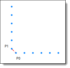
This option allows you to use the first target of drivers as origin.
For example, if you make a point P0 and repeat it in order to get P1, P2, ..., Pn, and if you make an axis between P0 and P1, if you serialize using the Interval mode, you'll get the axes A1(P1,P2), A2(P2,P3)...An-1(Pn-1,Pn).
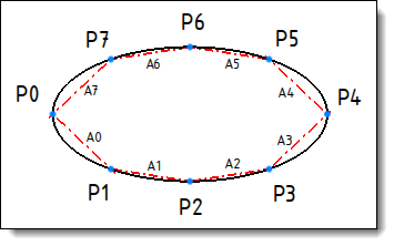
In addition, the Loop option allows you to go back on the origin P0.
|
|
|
|
|
Original entities (points + axis) |
Serialization using the Interval mode |
Serialization using the Interval mode with the Loop option. |
Multiplier drivers:
When a multiplier driver is defined, you get the serial copies corresponding to all the possible combinations of the "n" targets provided by the primary drivers and the "m" targets provided by the multiplier drivers.
For example, if you have the points P0 and Q0 repeated in P1, ..., Pn (primary drivers) and Q1, ..., Qn (multiplier drivers) and you make an axis between P0 and Q0, if you serialize it, you'll get the following axes:
|
A(P1,Q0) |
A(P2,Q0) |
... |
A(Pn,Q0) |
|
|
A(P0,Q1) |
A(P1,Q1) |
A(P2,Q1) |
... |
A(Pn,Q1) |
|
... |
||||
|
A(P0,Qm) |
A(P1,Qm) |
A(P2,Qm) |
... |
A(Pn,Qm) |
Create folders:
The entities created by the serialization can be grouped into sub-folders when the type supports this feature.
For example, the axis entities created by Serialization1 serialization operation are stored in the Axes (Serialization 1) folder of the Axes folder of the document.
Multiple serialization:
You can serialize several serializable operations at once, for this, you just have to select them in the list of operation to serialize.
In this case, the result of the serial copies can be used as driver for the other.
If you serialize a drilling and the operation which create an axis that references the cylindrical face of the drilling at once, the serial copy "i" of the axis creation will reference the face created by the serial copy "i" of the drilling.
Composite serialization:
When you select a composite operation which contains sub-operations in order to serialize it, sub-operations that can be serialized are also selected in the list, so it brings us back to the case of a multiple serialization.
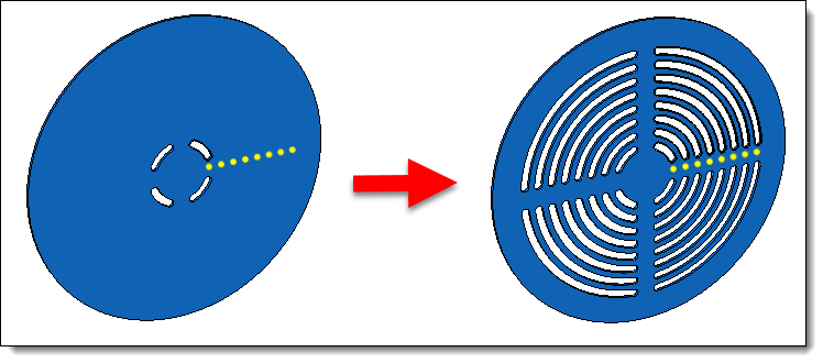
This case occurs when you want to serialize a pocket, its sketch is also automatically selected. You can remove it from the selection list if you don't want to serialize it.
 |
|
Example of a serialization of a pocket and its sketch into a Part document. |
De-ativation / activation
The Deactivate contextual command allows you to remove a copy of the series.
And you can to get back to the previous state with the Activate contextual command.
Deserialization / re-serialization
The Deserialize contextual command allows you to unserialize the serial copy. Then, the operation can be edited in order to be modified manually, it allows you to manage the exceptions.
And you can to get back to the previous state with the Reserialize contextual command.
Exploding
A serialization can be exploded thanks to the Explode contextual command.
Then the serialization operation is deleted but the serial copies are kept and they can be edited and deleted as well.