Swept
|
|
Swept |
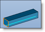
This command allows you to create a surface or solid shape by making one or more sections (open or closed) run along one or two trajectories.
Creation Stages / Use:
Click the icon or select the Surface > Swept... command from the drop-down menu.
Select the path or paths.
Then select the sections and their hooking points on the paths.
Available Options:
Paths:
|
|
This path corresponds to the trajectory followed by the sections in order to generate the surface.
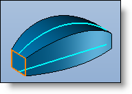
By checking the "Second path" check box, you can select a second trajectory. The shape is thus created by making the sections travel between two paths by applying a scale on the sections in order to follow the evolution of the paths.
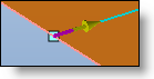
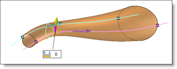
An arrow is hooked to the start of each path and thus indicates the travel direction. When two paths are used, the travel directions must be the same on each path. To invert the direction, simply double-click the arrow of the path in question.
|
Sections:
|
|
This option allows you to define the section(s) of the swept shape.
The sections must be designed in place. They must be planar and all be open or all be closed
For each section, it is necessary to define: - the profile to use as a section - its position and hooking point on each path.
The positioning point corresponds to the point that will act as a reference to calculate the movement of the section along the path.
The "Automatic hooking" allows you to automatically use the intersection point, detected between the plane of the section and the path, as the positioning point.
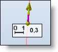
On each section an origin and a "drawing direction" of this profile represented by a point and arrow are defined.
The coefficient (variable from 0 to 1) determines the origin position of the profile (0: at the start; 1: at the end). Double-click the numeric value to modify it.
By double-clicking the small symbol in front of the coefficient, you can change the definition mode of the origin position.
The "point" mode allows you to select a point on the profile as being the new origin rather than using a coefficient.
In order for the swept shape to be created correctly and for it not to twist, the section origins must be aligned. |
Alignment:
|
|
This option allows you to define how the section travels along the path.
You will find more options on the Section alignment page. |
Surface:
|
|
By checking this option, the shape obtained will be a hollow surface without thickness and not a full shape. |
Limits:
|
|
This option allows to define limits of a swept surface by adding start and end points on each path.
|
Advanced Options:
|
|
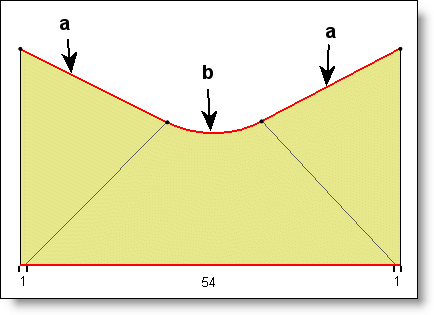
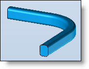
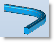
Mixing: This option allows you to determine the manner in which the shape changes from one section to another. The details explaining this mode are provided on the page: Section mixing.
Repair self-intersections: This option deletes auto-intersections between surfaces of the shape when this is the case.
Create sections: This option allows to create different sections of the surface to create. The number of wanted sections has to be entered. |