Pipe
|
Pipe |
This command allows you to create a surface shape or solid shape by making a selection (opened or closed) run along a trajectory.
Creation Stages / Use:
Click on the icon or choose
the command Surface >
Pipe... or from the drop down menu (or Modeling
> Local Shapes > Pipe in the assembly document).
Select the type of piped shape you wish to create.
Wire shape: |
|
Tube shape. |
|
Swept section. |
|
Select the path (or trajectory)
Then define the parameters according to the type of pipe chosen in stage 1
Available Options:
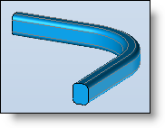
 Wire shape:
|
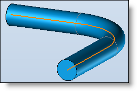
This mode allows you to create a wire with the desired diameter along a path.
If you check the Surfacic check box, the shape obtained will be a hollow shape without thickness and will not be a full wire. |
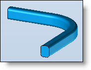
 Tube shape:
|
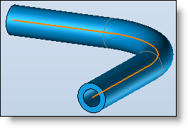
This mode allows you to create a tube with the desired diameter and thickness.
|
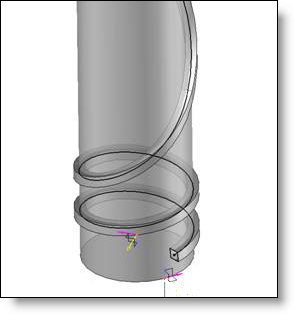
 Swept section:
|
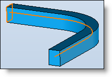
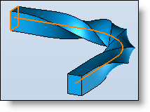
This mode creates a shape by making a section run along a path.
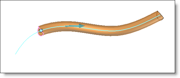
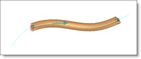
The Invert path option inverts the direction of the course along the path.
On an open path, the section must be positioned on one of the extremities. On a closed path, the Path origin option allows you to define the path origin which must be defined at the section in order to obtain a coherent result.
Section: The section can be designed in place by clickng the "+". It can be opened or closed.
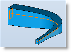
Section position: This option allows to specify the section position on the path, even if it is opened. It allows to create a pipe without having to position the section on the origin. If the section is not planar, the user has to specify the position on the path to obtain the wanted result.
Alignment: This command allows you to define how the section travels along the path.
You will find more details about this option on the Section alignment page.
Surface: By checking this option, the shape obtained will be a hollow surface without thickness and not a full shape. |
Advanced Options:
|
Corners type: If the path is not continue in tangency, corners can be sharp or rounded.
Simplify the geometry: This option allows to convert to flat, cylindrical or conical faces, faces of the pipe which are similar.
Repair self-intersections: This option deletes the self-intersections between faces of the shape.
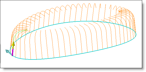
Create sections: This option allows to create different sections of the surface to create. The number of wanted sections has to be entered.
|
Limits:
|
This option allows you to define pipe limits by adding a start and an end point on the path.
The start point can be the section origin.
|
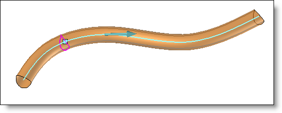
Twist (only for pipe on section):
|
This option allows you to apply a rotation to the section when sweeping along the path.
The Initial length and Final length options determine the length at the path start and end on which the section will not be turning. The rotation is therefore applied along the remaining length of the two.
The Initial angle and Final angle options determine the angular orientation of the section at the path start and end.
You can provide a final angle greater than 360°. In this case, the section will make more than one turn around the path.
|
Scale (only for pipe on section):
|
This option allows you to apply a reduction or increase of the size of the section during the sweeping along the path.
The Initial length and Final length options determine the length at the path start and end on which the section will not be changing. The reduction/increase of size is therefore applied on the length remaining between the two.
The Initial factor and Final factor options determine the scale factor of the section at the path start and end.
|