Pattern on profile
|
|
Pattern on profile |
This command can create a pattern on a profile.
Creation stages / Use:
Click the icon or select Construction > Patterns > Pattern on Profile... from the drop-down menu.
Select the profile.
Select the pattern's starting point, if it is different than the profile's starting point.
Select the pattern's end point, if it is different than the profile's end point.
Enter the desired number. Patterns cannot be outside of the profile. If the value is too large, patterns will often be ignored. The calculation is done as follows: Spacing * (total number -1) must be less than the length between the patterns start and end points.. If no value is entered, the total number will be defined by TopSolid based on other parameters (spacing, etc.).
Select a spacing type.
|
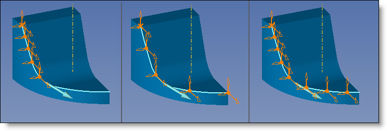
The spacing is defined by the angles by selecting an axis of rotation. Check or uncheck spacing angle and enter a value.
In the example below, the axis of rotation is the yellow axis. |
|
|
Total count = 5 and spacing angle = 10°. Total count = 5 and spacing angle is grayed. Total count is grayed and spacing angle = 10°. |
|
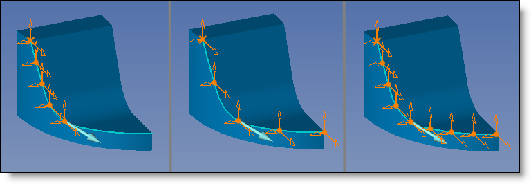
The spacing is defined by the spacing distance. Check or uncheck spacing distance and enter a value.
|
|
|
Total count=5 and spacing distance=30mm. total count=5 and spacing distance is grayed. total count is grayed and spacing distance = 30mm. |
|
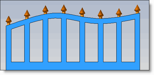
The spacing is defined according to a direction, not the curve. For example, ornamental spikes at the top of a portal will be defined according to the horizontal direction (like the spacing of bars), not according to the curvature. |
|
|
|
|
Spacing is defined by the spacing length. Unlike the distance, which is a straight line from one point to another, the length follows the profile. Check or uncheck spacing length and enter a value.
|
|
|
Total number=5 and spacing length=30mm. total number=5 and spacing length grayed. total number grayed and spacing length= 30mm. |
|
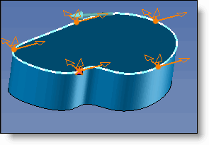
When the profile is more complex (ellipse, spline, etc.), the processing time may be longer with the spacing types above. The parameter type is faster. In this case, enter the total count. |
|
|
|
Choose an orientation.
|
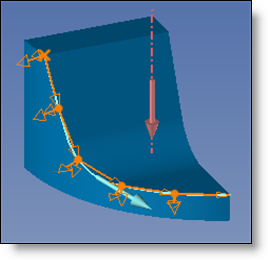
This orientation guides the frame in the direction of the next frame, which is very useful for chain links, for example. The vertical axis chosen for this capture is the Y axis.
|
|
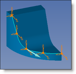
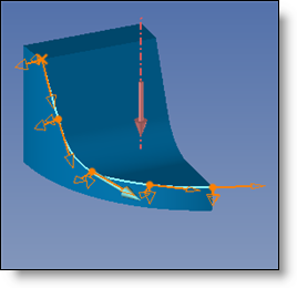
The orientation does not change. It remains constant with respect to the first.
|
|
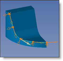
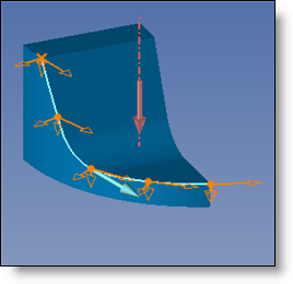
The Frenet frame is "supported" by the tangent and curvature of the profile.
|
|
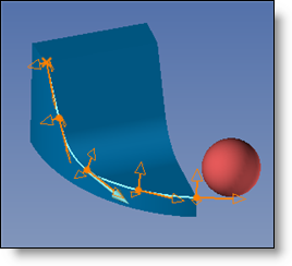
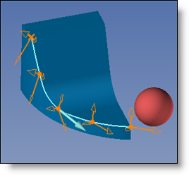
Select the shape. The pattern moves, maintaining a normal orientation to the shape. (the sphere in this example).
|
|
Select a vertical direction. The pattern moves, maintaining a normal orientation in that direction.
|
|
Select a vertical direction. The pattern moves, maintaining a vertical orientation with respect to that direction.
|
|
Select the shape. The pattern moves, maintaining a vertical orientation with respect to that shape.
|
|
|
|
|
|
- If the first total count is 1, there is no repetition. - If the second total number is 1, the pattern is equivalent to the simple version (circle). |