Circle involute
|
Circle involute |
This command can be used to create a tooth flank to model gears and pinions
Creation stages / Use:
Select the 2D sketch > Operations > Circle involute... command from the drop-down menu.
Enter the base diameter value (primitive diameter multiplied by the cosinus of the pressure angle) .
Enter the start diameter value (root diameter).
Enter the end diameter value (outside diameter).
Specify the center point for these circles.
Specify the passing point (point on the base circle).
|
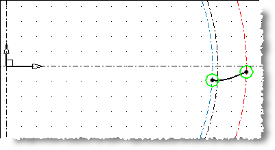
Example of a circle involute regarding the base diameter (in black), the start diameter (in blue) and the end diameter (in red). |
|
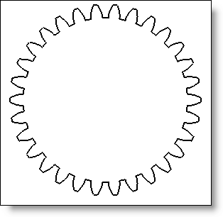
To create the complete pinion from the circle involute:
|
|
Available Options:
Linear Tolerance:
|
Allows to modify the calculation accuracy of the tooth flank (0.01mm by default). |