|
Cross Section Polygon |
This command allows to create a cross section polygon that can be used during the creation of a cross section in the same document or in another document.
The creation of the cross section polygon is a wizard with 3 stages:
Definition of the cross section polygon properties (name, type, reference view).
Creation of the cross section polygon using the sketch commands.
Definition of the cross section attributes (cross section name, depth, style, font, height,...)
This command is the first stage of the wizard and allows you to define the cross section polygon properties.
Creation stages / Use:
Select the View > Cross Section Polygon... command from the drop-down menu.
Enter the name of the cross section polygon, this name will be used to store the cross section polygon in the Entities tree.
Select the cross section polygon mode:
Manual: Allows to create an horizontal or vertical cross section polygon or a contour (the start and end segments of the contour must be parallel). |
|
Like: Allows to retrieve an existing cross section polygon.
Profile geometry, cutting depth, cross section type (standard, aligned section, ...) partial or complete cross section and text position, if it is manually moved, are recovered. The style of polygon cross section is the default style of the document. |
Select the cross section type:
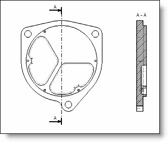
Standard: allows to create an horizontal or vertical cross section or a cross section using a cross section polygon created by the contour command. |
|
|
|
|
Standard cross section example |
|
|
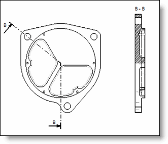
Aligned section. |
|
|
|
|
Aligned section example |
Valid the dialog to access to the second stage that allows you to create the cross section polygon using the sketch commands.
At least, you have to define the cross section polygon attributes.
|