Dimension
|
|
Dimension |
This command allows you to create toleranced dimensions by pressing the 3D geometry. This dimension will be visible when exporting the part if the chosen format supports 3D annotations.
Creation stages / Use:
Click the icon or select Tools > Annotations > Dimension... command from the drop-down menu.
Select the plane on which to "write" the dimension.
Validate by clicking  .
.
|
|
|
|
|
|
Available Options:
Text:
|
|
|
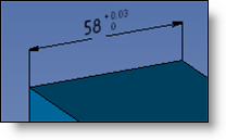
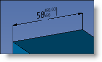
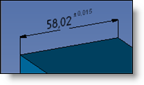
Tolerances:
|
|
|
|
Upper and Lower Spreads. |
|
|
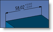
Symmetrical Spreads. |
|
|
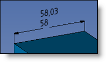
Minimum and Maximum Values. |
|
|
Medium Spread. |
|
|
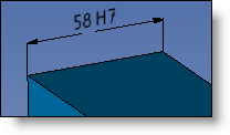
Quality Symbol. |
|
|
Quality and Upper and Lower Spreads. |
|
|
Quality and Minimum and Maximum Values. |
|
|
Exponent Medium Spread. |
|