Slot


Links/Videos:


This command produces a slot (material removal) based on a sketch.


Creation stages / Use:


Click the icon or select the Sheet metal > Slot... command from the drop-down menu.


  1. Select the slot type to achieve.


Path:

  • Select one or several path(s) (segment, profile or section created before). For each path selected, the position of the slot can be selected (right, center or left) in relation to the path and the direction which will be used to position any extremities.

  • Enter the high and low overthicknesses. To image the overthickness, the slot can be an extruded then substracted rectangle. If there is not overthickness, the extrusion is done at the value of the sheet metal thickness. It may cause problems in some cases.

By 2 points:

  • Select the 2 end points.

  • Select the position of the slot in relation to 2 points.

  • Enter the high and low overthicknesses. To image the overthickness, the slot can be an extruded then substracted rectangle. If there is not overthickness, the extrusion is done at the value of the sheet metal thickness. It may cause problems in some cases.

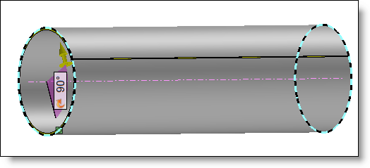
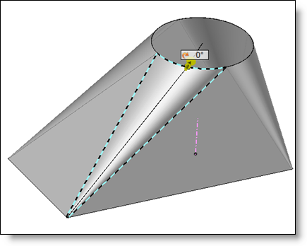
Open: This mode is intended for easily opening parts for which the initial shape is comparable to a tube (tubes or transition shapes).

  • If Plane is selected: From a face, an axis and a point, the slot is made in the passing plane by the axis and the point. If the selected face can provide an axis, the reference axis is automatically taken. If the selected face has a peak connected to a lateral face, it is automatically taken as the reference point. This point also defines the complementary rotation origin of the cutting plane.

  • If Iso Parametric is selected: The slot is positioned according to the "pertinent" generator allowing you to correctly open the selected face. This mode is intended for opening developable faces such as the transition cones of hoppers.

  • Select the support face.

  • Select the slot axis.

  • Select a point if necessary.

  • Enter an angle.

  • Select the position of the slot in relation to the axis.


  1. Select the shape to modify.

  2. Enter the slot width value.

  3. Validate the creation of the slot with the button.


A slot can be produced on a lateral face, the depth is then equal to the sheet thickness.


Available options (For path and By 2 points):


By default, the length of the slot is equal to the length of the path, at each extremity, you can either extend the slot by a certain value (extension mode), or position the corner reliefs (spherical or cubic).


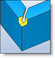
Example of slot with extension and spherical corner relief


If you select several paths, the extremities of each path will be the same type, the extremities of the different paths selected cannot be disassociated, in this case, it is advised to carry out several slotting operations.