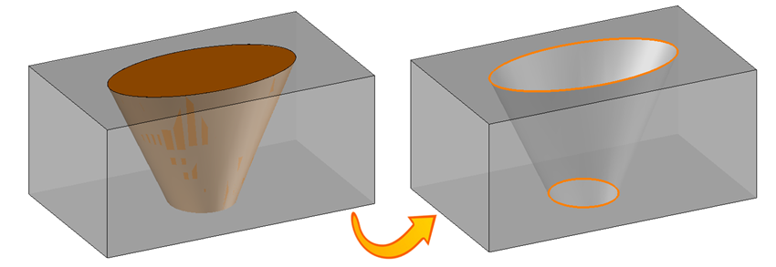
Wire cut
|
|
Wire cut |
For the small parts with sharp angles or really small internal radius this cut allows to :
Case of a die :
To get rid of a piece of the part by creating a contouring tool path on the geometry or by creating a destruction tool path on the geometry.
Case of a punch :
To cut this one.
 |
We can choose the kind of cut in the operation label.
3 kinds of cut by contouring :
|
|
Full cutting This cut allows to define a tool path all around the border of the geometry. It is used to make a precise finishing path (without falling mark) or when the falling part is already clamped.
|
|
|
Partial cutting This cut allows to define a tool path on all the geometry exept the glue.
|
|
|
Falling part cutting This cut allows to define a tool path only on the geometry's glue.It is mainly use after a partial cut to release the part (after changing the clamping system).
|
One kind of destruction cut :
|
|
Destruction This cut allows to define a tool path to fully remove the material situated inside the geometry to machine (mainly use on small pockets like ejector holes as it avoid to manage a fall).The tool path is similar to a spiral pocketing tool path or to a morphing (by taking into account the fact of not bringing down fall!)
|
Simply select on the part the geometry (faces) to machine.TopSolid automatically defines the geometry to machine.
 |
It is possible to define beforehand the geometry to machine with the function geometry. The interest is to define the characteristics of the geometry before using the cut function, to synchronize the machining between two curves, give a threading point, give a retract point, to define a length of glue …
|
Which geometry to use :
 |
Profile The cut following a profile is a straight cut, this operation is going to follow the curve defined by the user with movements following two axis. A draft angle is possible to do a simple 4 axis cut. |
 |
Two profiles The cut following two profiles is useful in the case of an evolutionary cut, this operation is going to follow curves defined by the user with movements following four axis or possibly two axis if the curves are the same. |
 |
Two profiles (on faces) It works the same way than the solution "two profiles", the two profiles are calculated in automatic by TopSolid. |
 It is possible to modify the geometry with
  +
+ 
 It is not possible to do a wire cut operation if no technology is selected.
The selection of the technological file allows TopSolid to define the machining parameters as the feed rate and the offsets (gap varying according to the spark) to use according to the following parameters:
Material
Material
Wire Diameter
Machine
Maximal scallop height
The technology is selected among the list of the available technological documents.
|
Wire technology G. Wire diameter Wire material Part material XS25C 0.25mm SW25X Copper Standard roughing cut CH19 Finishing cut CH23 XS25F 0.25mm SW25X Graphite XS25L 0.25mm SW25X Aluminium XS25v 0.25mm SW25X Steel XS25W 0.25mm SW25X Carbide XS25Fx 0.25mm SW25X Steel |
 The "filter" button at the top right of the screen allows to select the criteria to simplify the technology search.
From the cutting menu or using the mouse (selecting a face with the right mouse button), select cutting.
A toolbar appears on the left of the screen, along with a label in the graphic area.
 |
You can then modify values by
By selecting the value to modify in the label. The label is the table shown in the image in the top right corner. All label values are fields available from one of the icons in the left section. These values are placed on the label for quicker access.
By opening one of the left section icons
|
|
Select Favorite
Instead of modifying n values, this option allows you to restore (or save) values that have already been entered.
|
|
|
|
Define Cutting Conditions for Operation
Use this icon to modify the cutting conditions of the current operation.
|
|
|
|
Define or add geometries to machine
Use this icon to select (or remove) machinable geometries. This geometry is automatically machined, by first selecting the geometry and right-clicking "Cutting". You do not have to access the icon to do this.
|
|
|
|
Define all machining settings
Each machining has specific settings. Use this icon to access all settings (like compensation method, altitudes, plunge modes, ...)
|
|
|
|
Define G Code settings
Use this icon to define which comment to use for the G-code or to decide which inclined plane matrices to use.
|
|
|
|
Define operation properties
Use this icon to define whether you would like to update the stock or calculate the result later.
|
|
|
|
Confirm
To confirm the current operation, pressing this icon to right-click outside the window and use the "OK" menu
|
|
|
|
Cancel
If you wish to cancel the operation, click this icon.
|
|
|
|
Preview
Allow to show or hide the synchronisations (wire passing point between the top and bottom head). When this is hidden, the syncronisation is not calculated (so faster ....).
|
|
|
|
Show Label
Allows to display or hide the graphic area label.
|
|
|
|
Editing update
Each time a setting is changed (such as the step over in destruction), all calculations for updating the hatching area and the tool path are triggered. The setting change may take a few moments. In several cases, settings must be modified before updating the calculations. For this, press this icon. In the case, the hatching area and tool path (for example) are not recalculated before pressing this icon again.
|
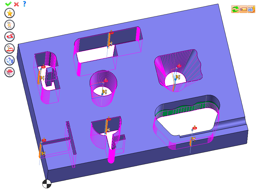
 Click the different areas in the image below
 |
|
|
|
|