Roughing
|
Roughing |
Icon Access: 
Location: Turning \ Roughing
Development:
Using a carting/facing roughing tool or a groove tool, remove the volume of material found between the solid representing the raw part and the solid representing the finished part, by taking into account possible stocks to leave.
Milling consists of completing several passes parallel to the Z-axis, facings parallel to the X-axis (or transversal passes using the grooving option), or successive passes parallel to a given direction or parallel to the milled profile.
Milling takes into account the possible bounds set by the user and the geometric characteristics of the tool (maximum plunge angle and forward angle).
There are two possible milling modes.
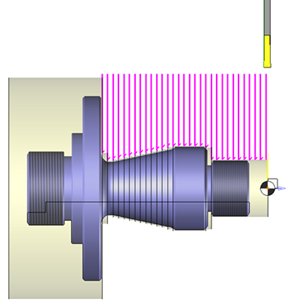
Paraxial roughing consists of successive parallel passes on the Z-axis, one direction or one contour. The pass can be constant or variable. These options are available in the main milling tab. This is the default milling type.
|
Groove roughing consists of a series of perpendicular passes on the Z-axis. This milling type can be enabled by double-clicking the tag icon box "Milling Type". |
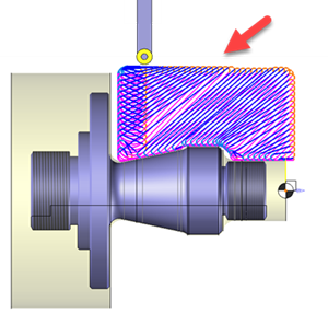
The Boost Turn roughing consists of a succession of passes in a free direction. The tool path is optimized for constant stock removal. This type of machining can be activated by double clicking on the tag icon "Type of machining". |
|
|
|
The roughing cycle is a multiple pass cycle whose depth at each pass can be constant or variable.
The roughing direction can be horizontal, that is, parallel to the Z-axis, vertical and therefore perpendicular to the Z-axis, or parallel to a given direction or a profile.
TopSolid'Cam's roughing module processes the entire volume of material found between solids that define the raw and finished parts, while taking into account possible stocks to leave, the plunge angle, and the forward clearance angle.
The plunge angle is identical to the HA angle and the forward angle is identical to the VA angle.
However, for a inner tool, the plunge angle is identical to the VA angle and the forward angle is identical to the HA angle.
Faces that make up the model to mill are cut into horizontal planes, parallel to the XY plane and to each other, to take into account the tool corner radius value and the stock to leave. These planes are regularly spaced at a value equal to the milling pitch (pass depth).
From the Turning menu or using the mouse (by selecting or not selecting a face with the right mouse button), select the "Roughing..." menu.
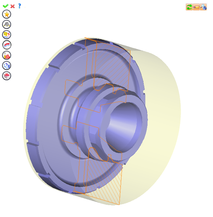
A toolbar appears on the left of the screen, along with a label in the graphic area.
You can then modify values by
By selecting the value to modify in the label. The label is the table shown in the image in the top right corner. All label values are fields available from one of the icons in the left section. These values are placed on the label for quicker access.
By selecting the values in the graphic area or by pulling the arrows. As with the values of the labels, these fields are present in one of the left section icons. These values are placed in the graphic area for quicker access.
By opening one of the left section icons.
|
Select Favorite
Instead of modifying n values, this option allows you to restore (or save) values that have already been entered.
|
|
Select the tool to use
By default, if the previous operation tool can be used, it is reused for this operation (the name of the tool appears in the graphic area next to
If the previous tool is not suitable or if this is the first operation, you must select a tool to validate the operation (
|
|
Define Cutting Conditions for Operation
Use this icon to modify the cutting conditions of the current operation.
|
|
Define or Add Geometries to Machine
Use this icon to select (or remove) machinable geometries. This geometry is automatically added, by first selecting the geometry and right-clicking "End c". You do not have to access the icon to do this.
Define Milling Boundaries
You can also apply trims (XYZ or contour) to the current operation.
|
|
Define All Milling Settings
Each milling has specific settings. Use this icon to access all settings (such as stocks to leave, altitudes, plunge modes, milling modes, etc.)
|
|
Define ISO File Settings
Use this icon to define which comment to use for the ISO code or to decide which inclined plane matrices to use.
|
|
Define colinear axis
This icon is available only if the current machine has colinear axis.With this icon it will then be possible to choose the axis drives by the operation.We also can choose the Z value of the fix axis. |
|
Define Operation Properties
Use this icon to define whether you would like to update the stock or calculate the result later.
|
|
Confirm
To confirm the current operation, pressing this icon to right-click outside the window and use the "OK" menu
|
|
Cancel
If you wish to cancel the operation, click this icon.
|
|
Preview
Display or hide the machining area. When this is hidden, this area is not calculated, and response times improve.
|
|
Show Label
Allows you to display or hide the graphic area label.
|
|
Editing Update
Each time a setting is changed (such as the axial depth), all calculations for updating the hatching area and the trajectory are triggered. The setting change may take a few moments. In several cases, settings must be modified before updating the calculations. For this, press this icon. In the case, the hatching area and trajectory (for example) are not recalculated before pressing this icon again.
|
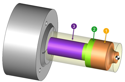
 Click the different areas in the image below
|
|
|
Visibility management when editing the operation: click on the icons below
Machine visibility |
WCS visibility |
Tool visibility |
Collision visibility |
Stock and finish visibility |
Tool paths visibility |
|
|
|
|
|
|
|
|


 Boost turning
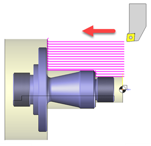


 )
) )
)


 All it takes is for the bodies to be in contact with each other.