![]()
Swarf machining
|
Swarf machining |
Icon Access: 
Location: 4D / 5D / Rolling Machining
Development:
Create a continuous 5 axes milling operation supported by surfaces or two curves, the goal being to keep the rolling part of the tool along the supporting surfaces or curves by changing axes A, B, or C.
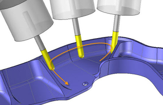
There are three methods for completing a 5 axes swarf machining based on the geometry to mill.
The choice of milling type is done in the label by double-clicking the icon that corresponds to the default milling type.
 We must always define the geometry to mill, this is why the geometry button has a star.

5 axes swarf machining takes into account the strokes of the machine. In some cases, you must go back up to return to the angular bound of the machine axes or unroll the cables.
 The 5 axes button defines all settings related to the five axes, such as:
Safety Shapes
Safety shapes (depending on the machine kinematic).
As such, the following is advised:
Parallelepiped for head-head machines.
Cylinder for table-head machines.
Plane for table-table machines.
Ascent Types
Angular limits and unrolling of cables
The angular limits are defined in the machine, but cannot be modified locally in the "Axis" angle.
Management of strokes when an angular stroke has been reached.
Lead / Lag and side angle
Select the milling method to complete the swarf
 "Face and Bottom" Method
It is used when millling is completed on several adjacent surfaces, therefore the isoparametrics are not forcibly linked.
The user starts by selecting the surfaces to mill and then defining the guide geometry that will orient the tool on the surface to mill.
For a supporting face, you must specify the radius of the fillet. Generally, you must define a radius greater or equal to the blend between the surfaces to mill and the supporting faces.
 "On Curves" Method
The manual mode is used in the event that face methods do not give the correct result. The user must construct two curves on which the tool will be supported in order to define the 5 axes trajectory.
For closed curves, you must verify the origin of the curves, which define the synchronization start and the lead/lag angle.
Often, it is recommended to smooth this curves in order to correctly synchronize the entire trajectory.
 "Face" Method
It is used when millling is completed on one surface or several adjacent surfaces, so the isoparametrics are well linked.
The user starts by selecting the surfaces to mill and then defining the milling direction and the tool orientation following the U or V ISO directions.
The two following icons allows us to select the necessary geometries for the machining. We can also modify the synchronisation if necessary.
|
Geometry Depending which kind of method we choose, we then just have to select the faces or curves to indicate the geometry needed for the tool path calculation.
|
|
Synchronisation There are 3 different methods for synchronisation. The aim is to choose the good one in order to correctly orient the tool all along the geometry. |
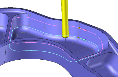
 Whatever method is used, to realize the swarf TopSolid always use 2 curves. The bottom curve (for example C1) et the top curve (for example If the selected method is based on faces TopSolid starts by calculating in automatic these two curves.
Once we have C1 and C2, TopSolid will synchronise one point of C1 with one of C2 to decide where the tool will be positioned.
Depending on which synchronisation method has been applied the result on the machine might be different.
A synchronisation between a point of C1 and a point of C2 will create a line between this two points which gives the tool position (on the machine the tool axis will be colinear to this axis).
Depending which synchronisation type has been selected the part won't be machine in the same way! It is then important to check the result before machining the part (a bad synchronisation can create an overcutting in the part even if we choose a swarf on faces).
Whatever the synchronization method used, in the case of a closed curve it is possible to modify the origin of the curve (start of the synchronization) with the icon 
Profile / Profile synchronisation |
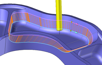
The synchronisation is automatically calculated regarding the length of each curve (C1 & C2). The point located at the middle of the length of C1 is then linked to the half of the length of C2.
|
Segment / Segment synchronisation |
In this case we must have the same number of entities on each geomtry.
|
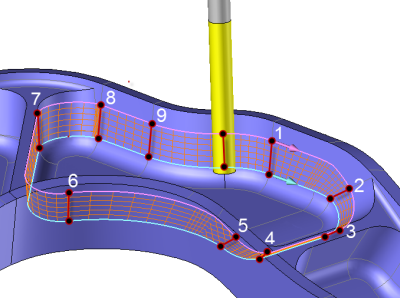
Point / Point synchronisation |
TopSolid automatically calculate a synchronisation (depending which computing mode we choose in the settings: parametric or curve length). It is possible to insert a couple of points on C1 & C2 (named 1 to 9 on our example). The following window appears at screen.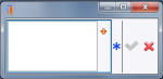 The points must be selected first on the bottom curbe and then on the top curve.
TopSolid colors in orange the curve on which must be selected the current point for the synchronization. |
,
 To add or delete a point right click on the label of a sync point and then choose the operation to make in the scroll menu.
| Points |
A toolbar appears on the left of the screen, along with a label in the graphic area.
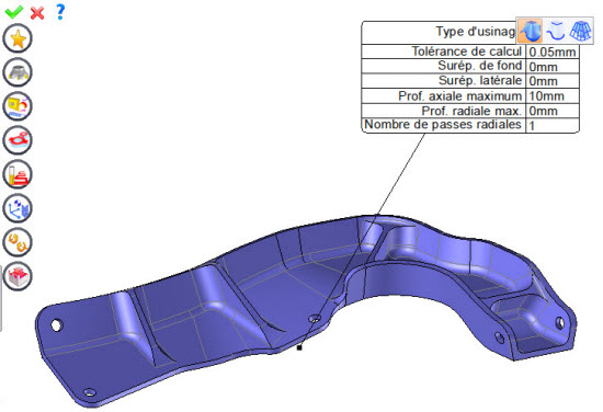
By selecting the value to modify in the label. The label is the table shown in the image in the top right corner. All label values are fields available from one of the icons in the left section. These values are placed on the label for quicker access.
By opening one of the left section icons.
|
Select Favorite
Instead of modifying n values, this option allows you to restore (or save) values that have already been entered.
|
|
Select the tool to use
By default, if the previous operation tool can be used, it is reused for this operation (the name of the tool appears in the graphic area next to
If the previous tool is not suitable or if this is the first operation, you must select a tool to validate the operation (
|
|
Define Cutting Conditions for Operation
Use this icon to modify the cutting conditions of the current operation.
|
|
Define or Add Geometries to Machine
Use this icon to select (or remove) machinable geometries. This geometry is automatically added, by first selecting the geometry and right-clicking "End Milling". You do not have to access the icon to do this.
Define Milling Boundaries
You can also apply trims (XYZ or contour) to the current operation.
|
|
Define All Milling Settings
Each milling has specific settings. Use this icon to access all settings (such as stocks to leave, altitudes, plunge modes, milling modes, etc.)
|
|
Define ISO File Settings
Use this icon to define which comment to use for the ISO code or to decide which inclined plane matrices to use.
|
|
Define colinear axis
This icon is available only if the current machine has colinear axis.With this icon it will then be possible to choose the axis drives by the operation.We also can choose the Z value of the fix axis. |
|
Define Settings for 5 Axes Use this icon to define the five axis milling settings. |
|
Define Operation Properties
Use this icon to define whether you would like to update the stock or calculate the result later.
|
|
Confirm
To confirm the current operation, pressing this icon to right-click outside the window and use the "OK" menu
|
|
Cancel
If you wish to cancel the operation, click this icon.
|
|
Preview
Display or hide the machining area. When this is hidden, this area is not calculated, and response times improve.
|
|
Show Label
Allows you to display or hide the graphic area label.
|
|
Editing Update
Each time a setting is changed (such as the axial depth), all calculations for updating the hatching area and the trajectory are triggered. The setting change may take a few moments. In several cases, settings must be modified before updating the calculations. For this, press this icon. In the case, the hatching area and trajectory (for example) are not recalculated before pressing this icon again.
|
 Visibility management when editing the operation: click on the icons below
Machine visibility |
WCS visibility |
Tool visibility |
Collision visibility |
Stock and finish visibility |
Tool paths visibility |
|
|
|
|
|
|


 )
) )
)


