Hub finishing
|
Hub finishing |
Automatically perform a native five-axis finishing of the bottom face (hub) of an impeller and/or a blisk.
On a given segment or up to the entire part to be machined.
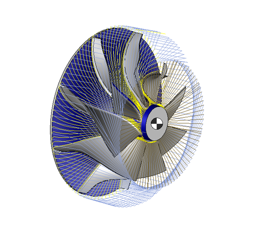
The hub finishing is based directly on the faces given in the geometry, taking into account possible collisions between the tool (between the tool tip and the mounting frame of the tool holder on the machine) and the finish.
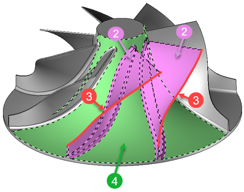
Multi-Blade machining is strictly limited to the area corresponding to the blades and areas within the blades.
To delimit the area to be machined, it is sufficient to distinguish three surface families:
In green the hub faces
In purple the blade faces (including the interpales if they exist)
In red the shroud faces
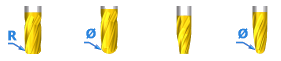
Only the following tools are supported by hub finishing machining
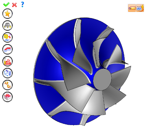
Using the 4D/5D menu, or the mouse, select the "Hub finishing" operation.
A toolbar appears on the left of the screen along with a label in the graphic area.
You can then modify values by:
By selecting the value to modify in the label. The label is the table shown in the image in the top right corner. All label values are fields available from one of the icons in the left section. These values are placed on the label for quicker access.
By opening one of the left section icons.
|
Select Favorite
Instead of modifying n values, this option allows you to restore (or save) values that have already been entered.
|
|
Select the tool to use
By default, if the previous operation tool can be used, it is reused for this operation (the name of the tool appears in the graphic area next to
If the previous tool is not suitable or if this is the first operation, you must select a tool to validate the operation (
|
|
Define Cutting Conditions for Operation
Use this icon to modify the cutting conditions of the current operation.
|
|
Define or Add Geometries to Machine
Use this icon to select (or remove) machinable geometries. This geometry is automatically added, by first selecting the geometry and right-clicking "End Milling". You do not have to access the icon to do this.
Define Milling Boundaries
You can also apply trims (XYZ or contour) to the current operation.
|
|
Define all milling settings
Each milling has specific settings. Use this icon to access all settings (such as stocks to leave, altitudes, plunge modes, milling modes, etc.)
|
|
Define ISO File Settings
Use this icon to define which comment to use for the ISO code or to decide which inclined plane matrices to use.
|
|
Define colinear axis
This icon is available only if the current machine has colinear axis.With this icon it will then be possible to choose the axis drives by the operation.We also can choose the Z value of the fix axis.
|
|
Allow us to add one or more axis on the current machining
For example on 4 and 5 axis machine, to have the possibility of doing radial or axial operations. |
|
Define Operation Properties
Use this icon to define whether you would like to update the stock or calculate the result later.
|
|
Confirm
To confirm the current operation, pressing this icon to right-click outside the window and use the "OK" menu
|
|
Cancel
If you wish to cancel the operation, click this icon.
|
|
Preview
Display or hide the machining area. When this is hidden, this area is not calculated, and response times improve.
|
|
Show Label
Allows you to display or hide the graphic area label.
|
 Click the different areas in the image below
Type of Machining |
|
Time |
10:05:00 |
|
|
|
|


 )
) )
)