
Milti-axis pocketing
|
Milti-axis pocketing |
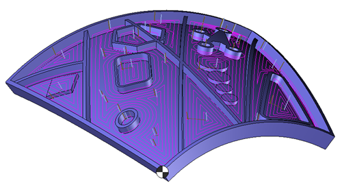
Multi-axis pocketing is a machining process based on machining cavities where the "floor, ceiling, and walls" are not necessarily in one plane.
IIt is possible to execute this multi-axis machining on any 5-axis machine.
The idea is to remove the material in pockets (selected geometries) following a calculated orientation.
The topological analysis engine analyzes the selected geometries to check if the generation of the tool path is possible.
If the geometry is correct, the algorithm automatically calculates the tool paths following the curvature of the selected faces while taking into account the material height and the bounding area imposed by the user.
Although the main interest is the machining of cavities, it is possible to perform a "pocket machining" to machine the interior and exterior depending on the case.
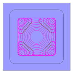
 An "Adaptive" machining mode similar to "Boost" machining is also available with this function.
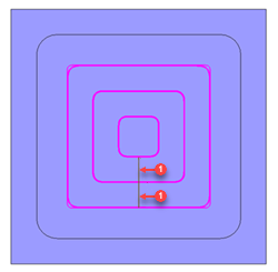
 Offset mode Offset mode |
 Adaptive mode Adaptive mode |
 |
 |
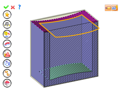
Simply select the bottom and top of the pocket so that the topological analysis recognizes the area to be machined.
The stock management in the function allows to determine automatically the height of the material to be machined and also to optimize the tool paths according to the existing stock at each axial pass.
It is necessary to manually set up the operation by selecting the bottom (1).
The ceiling (2), et eventually a bouding curve (3) which defines virtual vertical walls to limit machining.
You can then modify values by:
By selecting the value to modify in the label. The label is the table shown in the image in the top right corner. All label values are fields available from one of the icons in the left section. These values are placed on the label for quicker access.
By opening one of the left section icons.
|
Select Favorite
Instead of modifying n values, this option allows you to restore (or save) values that have already been entered.
|
|
Select the tool to use
By default, if the previous operation tool can be used, it is reused for this operation (the name of the tool appears in the graphic area next to
If the previous tool is not suitable or if this is the first operation, you must select a tool to validate the operation (
|
|
Define Cutting Conditions for Operation
Use this icon to modify the cutting conditions of the current operation.
|
|
Define or Add Geometries to Machine
Use this icon to select (or remove) machinable geometries. This geometry is automatically added, by first selecting the geometry and right-clicking "End Milling". You do not have to access the icon to do this.
Define Milling Boundaries
You can also apply trims (XYZ or contour) to the current operation.
|
|
Define all milling settings
Each milling has specific settings. Use this icon to access all settings (such as stocks to leave, altitudes, plunge modes, milling modes, etc.)
|
|
Define ISO File Settings
Use this icon to define which comment to use for the ISO code or to decide which inclined plane matrices to use.
|
|
Define colinear axis
This icon is available only if the current machine has colinear axis.With this icon it will then be possible to choose the axis drives by the operation.We also can choose the Z value of the fix axis.
|
|
Allow us to add one or more axis on the current machining
For example on 4 and 5 axis machine, to have the possibility of doing radial or axial operations. |
|
Define Operation Properties
Use this icon to define whether you would like to update the stock or calculate the result later.
|
|
Confirm
To confirm the current operation, pressing this icon to right-click outside the window and use the "OK" menu
|
|
Cancel
If you wish to cancel the operation, click this icon.
|
|
Preview
Display or hide the machining area. When this is hidden, this area is not calculated, and response times improve.
|
|
Show Label
Allows you to display or hide the graphic area label.
|
 Click the different areas in the image below
|
|
Time |
00:00:10 |
Étendre au brut |
|
|
|


 )
) )
)


