![]()
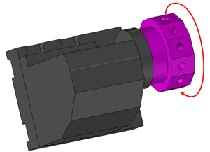
Virtual jog
|
Virtual jog |
Realise a sequence of basic actions that describe specific movements or Iso codes to send on the machine.
It could be for example to park a turret on a safety position before transfering the part, to simulate a specific operation and send the corresponding G-code without any treatment with the Postprocessor.
Those manual operations don't necessary need tools or cutting conditions (park a turret at a safety place doesn't need a tool call) so the tool and cutting conditions are optional.
It is why a box to tick appears on the tool choice and cutting conditions.
![]() Choice of Tool
Choice of Tool
Like said previously the tool choice is optional. To select the tool we first need to tick the box.
Of course if the tool box has been ticken we must choose one to validate.
![]()
![]() Choice of the cutting conditions
Choice of the cutting conditions
Like for the tool, it's optional.
 Choice of the part
Allows you to select the part on which to perform the operation. In the case of one program generated by part TopSolid'Cam will then add this operation on the correct program.
 Operation choice
The operation that can be perform with the function virtual jog are listed in the "settings" icon.
Simply choose the operation in the list under the title "type".
Operation Settings Jog items: Type Value
Activate simulation? Activate the G code Approach to hold part Direct machine block Post processor command G Function M Function Turret indexation Machine axis movement Relative Movement Movement on Coordinates Movement on a safety shape Movement on a safety plane Movement on Point Movement on tool change... Synchronization point User Comment Hold/Release part Follow profile Delay Part pulling Part transfer |
By default the simulation and the G-code output are activated by a virtual jog.They can still be disabled.
It is also possible to add direct blocks or a sub-program in the G-code.
|
||||||||||||||||||||||||||||||||||||||||||||||||||||||||||||||||||||||||||||||||||||||||||||||||||||||||||||||||||||||||||||||||||||||||||||
 |
Start a new direct machine bloc. |
 |
Insert machine bloc from a text document. |
 |
Save the machine bloc in a text document. |
We can also add a time then the total time of the whole process will include this kind of operations. These times are also visible in the scenario.
Give a specific instruction to the Post-Processor using a keyword called Pp word.(of course this keyword must be known by the Post- Processor).
It is possible to choose many operations and realize them with successive simple operations.If the operations are basic like add a G or M code we then just have to enter the desired code in the "value" column.
It is possible to define a turret indexation (if we need for example to call an empty pocket before park the turret under the spindle).
|
Machine axis movement
Resolve machine axis position
Position of Axes
Feed rate Rapid |
 The button "Resolve machine axis state" has been made to assist the user defining the coordinates.
It allows to select a reference point on the machine moving elements and a point on the fix element. Then it will define the axis to move to obtain that movement.
It is possible to do a relative movement. That means a movement from the actual position of the tool holder (part holder).
Just first choose a WCS using the tool holder and then indicates the moving distance on the axis.
It is possible to make a movement on coordinates. That means a movement regarding a reference frame.
Just first choose a WCS using the tool holder to move and then indicates the coordinates to reach regarding a reference frame.
Orientation frame:
Machine Part WCS |
It is then possible to do a movement on a safety element. In that case a tool must be used in the virtual jog (in the case of a safety shape the tool must be inside the shape).
It is then possible to do a movement on a safety plane.
It is possible to do a movement on a point or on the tool change point.
It is possible to define a target and source synchronization point by a same name to automate the link movements in the scenario.
Synchronization point Name Type : None Source Target |
It is possible to add user comment. It will be shown as comment in the G-code output.
It is possible to manage the parts displayed by using the virtual jog "Hold\Release part".
By default all the part are displayed during the simulation. As soon as a release part operation is used on a part holder the part became invisible during the simulation.
This option is use to simulate the part transfer on a two-spindle lathe.
It is possible to follow an existing profile.
It is possible to put a delay (in time or number of turns).
It is possible to move the synchronous spindle to come grab the part on the main spindle.
A first movement is done in rapid feed rate and a second to grab the part is done in machining feed rate.
Approach to hold part Rapid feed rate to machining feed rate
Offset
Grab the part
Offset |
It is possible to pull the part, that is to say to shift it linearly in the main spindle..
This operation is ofter preceded by an operation to grab the part by the synchronous spindle.
Part pulling Part pulling Shift of part size Offset
Create shifted origins |
It is possible to do a part transfer on the synchronous spindle..
This operation is ofter preceded by an operation to grab the part by the synchronous spindle.
![]()

Define colinear axis
This icon is available only if the current machine has colinear axis.
With this icon it will then be possible to choose the axis drives by the operation.
We also can choose the Z value of the fix axis.
 Choose a WCS
For some virtual jog, a WCS is required
Relative movements
Movement on coordinates
Movement on a safety shape
Movement on a safety plane
Movement on point
Movement to the tool change position
Like the link movements. this coordinates may be given refering three diferent frame:
 |
According to the machine origin |
 |
According to the part origin |
 |
According to the machining origin |

When editing an element of the jog, TopSolid jumps at the end of the last operation for the simulation.
As soon as we validate a new operation this one will be simulated.
From the element list of the Jog, it is possible to simulate movement operations at any time by clicking on the header of the line.A second click during the simulation will stop it and position the machine at the end of this one.
The "value" column" allows to quickly show the path of the whole actions and a single click on this column allows to open the parameters edition concerning the selected element of the jog.
 Attribute
 It is possible to request the stock update during a movement to a point or following a profile.
 The stock update will be done only if the feed rate is not in rapid and if the tool rotation is asked.
|
But in some cases it is not necessary to use a link movement because it is the user himself who will have defined these movements in the virtual jog (such as with direct blocks or machine axis movements). In this case it is necessary to switch in the label from "automatic" mode to "no link movements" mode.
|
 Visibility management when editing the operation: click on the icons below
Machine visibility |
WCS visibility |
Tool visibility |
Collision visibility |
Tool paths visibility |
|
|
|
|
|