
Pocketing by plunges
|
Pocketing by plunges |
Remove any material perpendicular to a face or contour between the finished part and the rough part by extending it to the horizontal limits of the rough part and observing any possible islands that may be found.
TopSolid performs the machining by a succession of plunges.
|
The pocketing by plunges processes faces with simple and complex outlines.Corners with a radius smaller than the tool radius or islands close to the outer edges do not interfere in any way with the calculation of the tool path. On the contrary TopSolid'Cam generates residual material that will be automatically recognized by remilling operations.
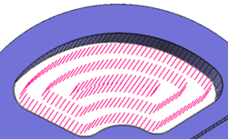
When configuring milling settings in dialog boxes, the actual machinable area is viewed by interactive hatching.
The plunging cycle breaks down the tool path of a classical pocketing operation and creates a succession of plunges at regular intervals.The interval is defined by the plunge step value.
Example of a classical pocketing in spiral and the same by plunging.
|
As for the classical pocketing there are 3 end milling strategies :
 |
Spiral mode:
|
 |
Sweeping mode:
 |
 |
Successive contouring
 |
From the 2D/3D menu or using the mouse (selecting a face with the right mouse button), select pocketing plunge.
A toolbar appears on the left of the screen, along with a label in the graphic area.

You can then modify values by
By selecting the value to modify in the label. The label is the table shown in the image in the top right corner. All label values are fields available from one of the icons in the left section. These values are placed on the label for quicker access.
By selecting the values in the graphic area or by pulling the arrows (the 2 fields have a value of 0.5 in the top image, above the hatching area). As with the values of the labels, these fields are present in one of the left section icons. These values are placed in the graphic area for quicker access.
By opening one of the left section icons.
|
Select Favorite
Instead of modifying n values, this option allows you to restore (or save) values that have already been entered.
|
|
Select the tool to use
By default, if the previous operation tool can be used, it is reused for this operation (the name of the tool appears in the graphic area next to
If the previous tool is not suitable or if this is the first operation, you must select a tool to validate the operation (
|
|
Define Cutting Conditions for Operation
Use this icon to modify the cutting conditions of the current operation.
|
|
Define or Add Geometries to Machine
Use this icon to select (or remove) machinable geometries. This geometry is automatically added, by first selecting the geometry and right-clicking "End Milling". You do not have to access the icon to do this.
Define Milling Boundaries
You can also apply trims (XYZ or contour) to the current operation.
|
|
Define all milling settings
Each milling has specific settings. Use this icon to access all settings (such as stocks to leave, altitudes, plunge modes, milling modes, etc.)
|
|
Define ISO File Settings
Use this icon to define which comment to use for the ISO code or to decide which inclined plane matrices to use.
|
|
Define colinear axis
This icon is available only if the current machine has colinear axis.With this icon it will then be possible to choose the axis drives by the operation.We also can choose the Z value of the fix axis.
|
|
Define Operation Properties
Use this icon to define whether you would like to update the stock or calculate the result later.
|
|
Confirm
To confirm the current operation, pressing this icon to right-click outside the window and use the "OK" menu
|
|
Cancel
If you wish to cancel the operation, click this icon.
|
|
Preview
Display or hide the machining area. When this is hidden, this area is not calculated, and response times improve.
|
|
Show Label
Allows you to display or hide the graphic area label.
|
|
Editing Update
Each time a setting is changed (such as the axial depth), all calculations for updating the hatching area and the trajectory are triggered. The setting change may take a few moments. In several cases, settings must be modified before updating the calculations. For this, press this icon. In the case, the hatching area and trajectory (for example) are not recalculated before pressing this icon again.
|
 Click the different areas in the image below
#1 |
|
Time |
01:05:00 |
Altitude... |
|
Side stock to leave on islands |
|
Plunge step |
|
Trajectory Preview |
Visibility management when editing the operation: click on the icons below
Machine visibility |
WCS visibility |
Tool visibility |
Collision visibility |
Stock and finish visibility |
Tool paths visibility |
|
|
|
|
|
|
|
|


 )
) )
)


