![]()
Control points
|
Control points |
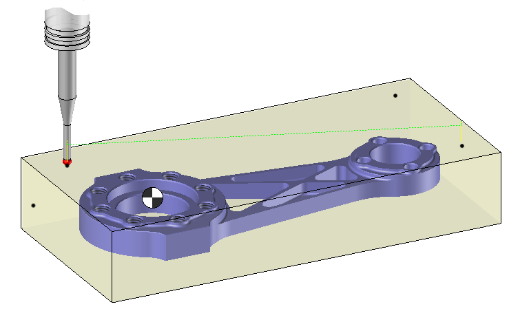
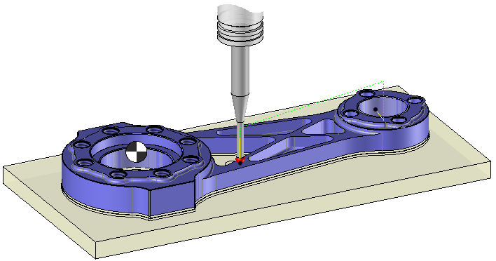
The aim is to control points on the finish or stock.
The tool will approach perpendicularly to the finish or stock in rapid feed rate and then in work feed rate to "touch" the desired point.
The post processor will then output movements in rapide and work feed rate (G1 & G0).
Control points on stock |
Control points on the finish part |
 |
 |
There are several control cycles avialable.Each cycle allows to control a particular geometry which may need several points to be control.
|
|
Individual points Allows to control one or many points. |
 |
Curve
Allow to control one or many curves. The selected profiles are discretized according to a discretization tolerance which is specified in the operation settings Tab. Then the points are projected on the nearest shape.
|

|
Cylinder Allow to control points on the side of a cylindrical boss or a cylindrical pocket to determine the center. Just click in the geometry tab on the internal or external face of the cylinder.
|

|
Rectangle
Allow to calculate the center of a rectangular boss or of a rectangular pocket and initialize its center as reference point.Just select in the geometry : - The four faces of the rectangular shape.Each face must be perpendicular to the last one and the next one. - The four edges of the rectangular shape.The faces must satisfied the constraints previously expressed. |

|
Corner Allow to control 2 points on two face which define a corner to determine the intersection point between the two faces. There is two different ways to select the geometry : - The edge at the intersection of the two faces of the corner (if existing). - The two faces of the corner.Those two faces must be planar and perpendicular between each other.
|

|
Slot Allow to control a point on each face of a slot to determine the center of this slot.Just select the 2 faces of the slot in the geometry. |
![]()
It is then possible to modify values by opening one of the icons on the left.
|
Select Favorite
Instead of modifying n values, this option allows you to restore (or save) values that have already been entered.
|
|
Select the tool to use
By default, if the previous operation tool can be used, it is reused for this operation (the name of the tool appears in the graphic area next to
If the previous tool is not suitable or if this is the first operation, you must select a tool to validate the operation (
|
|
Define Cutting Conditions for Operation
Use this icon to modify the cutting conditions of the current operation.
|
|
Define or add geometries to control
Use this icon to select (or remove) the points to control.
|
|
Define all milling settings
Each milling has specific settings. Use this icon to access all settings (such as stocks to leave, altitudes, plunge modes, milling modes, etc.)
|
|
Define ISO File Settings
Use this icon to define which comment to use for the ISO code or to decide which inclined plane matrices to use.
|
|
Define Operation Properties
Use this icon to define whether you would like to update the stock or calculate the result later.
|
|
Confirm
To confirm the current operation, press this icon right-click outside the window and use the "OK" menu
|
|
Cancel
If you wish to cancel the operation, click this icon.
|
|
Editing Update
Each time a setting is changed (such as the axial depth), all calculations for updating the hatching area and the trajectory are triggered. The setting change may take a few moments. In several cases, settings must be modified before updating the calculations. For this, press this icon. In the case, the hatching area and trajectory (for example) are not recalculated before pressing this icon again.
|
 Click the different areas in the image below
Type of Machining |
|
Time |
|
Control depth |
Visibility management when editing the operation: click on the icons below
Machine visibility |
WCS visibility |
Tool visibility |
Collision visibility |
Stock and finish visibility |
Tool paths visibility |
|
|
|
|
|
|


 )
) )
)


