![]()
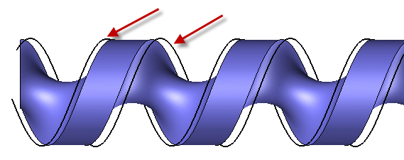
Isoparametric curve on parallel
|
|
Isoparametric curve on parallel |
Create one or more isoparametric curves taking into account the tool of the screw milling operation. We can also take into account the center offset.
It's paticularly true for screw milling, having a constant or evolving step regardless of the screw body shape (cylindrical or conical,...) and the helix section.
This function can also be used to quickly create one or more tilting curves for five axes operations (this avoids to use the isoparametric function in Design and have to do some transformations to have it at the good place).
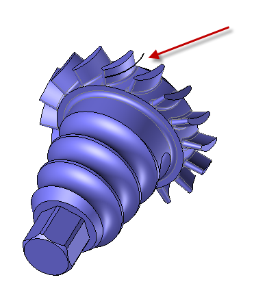
First, we have to define the reference surface, the tool (ball nose, radiused mill or side mill) as well as the isoparametric parameters.
|
|
|
Once the face is selected and the isoparametric parameters settled it's required to: 1- Activate the option "Around axis" 2- Select the part revolution axis. This one is either X+ or Y+. 3- Enter the center offset value then select the reference surface. In this case, the vertical is necessarily Z+ and we take into account the fourth revolution axis. 4- Validate the parameters by clicking on the green check mark. |
|
Once the face is selected and the isoparametric parameters settled it's required to:
1- Select the vertical direction. Usually it's Z+. 2- Validate the parameters by clicking on the green check mark. |
|
|
|


