
Chamfering
|
Chamfering |
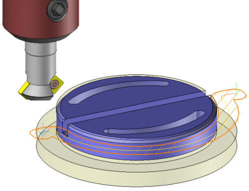
Machine a chamfer or a back chamfer (depending the selected face) by using an appropriate tool like a chamfer mill or a back chamfer mill.
TopSolid'Cam recommends a number of Z passes based on the material to remove and the cutting conditions of the called tool.
|
|
 |
 |
The topology analysis engine searches all faces adjacent to the selected face in order to define a closed path whenever possible. The chamfering function is similar to the contouring function. The starting point of the chamfering operation is always proposed in the center of the face designated by the operator. The type of lead in and lead out and the various plunge modes can be modified when defining the operation.
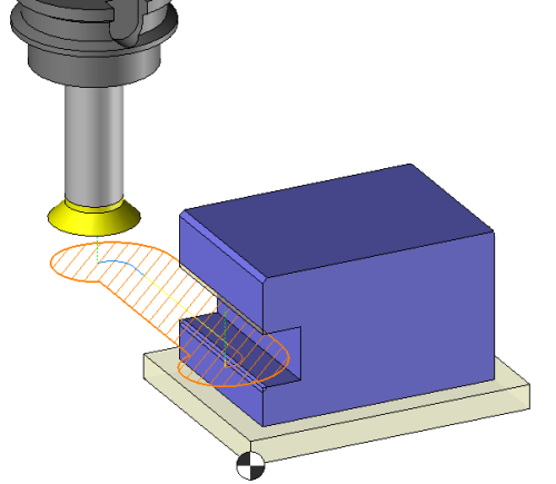
Machining on profile.
The tool choice will define if it is a chamfer or a back chamfer operation.
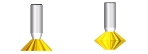
 For a double chamfer mill the chamfer or back chamfer option is available in the label.
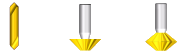
The profile positioning options and the parameters :"Flat length", "depth" will be used to define the geometry of the chamfer.
 |
The sketch is on the bottom of the chamfer |
 |
The sketch is on the top of the chamfer |
 |
The skecth is on the fictive edge of the chamfer |
The algorithm also manages corners of which the minimum radius is less than the tool radius.
A chamfering operation assumes a plunge that can be done in or outside the material! To do this, several plunge modes are available, based on the tool selected by the operator. In the case of a full material, quick feed rate or feed rate vertical plunge, the user can define a plunge point or use the point proposed by TopSolid'Cam.
From the 2D/3D menu or using the mouse (selecting a face with the right mouse button), select Chamfering.
A toolbar appears on the left of the screen, along with a label in the graphic area.
|
You can then modify values by
By selecting the value to modify in the label. The label is the table shown in the image in the top right corner. All label values are fields available from one of the icons in the left section. These values are placed on the label for quicker access.
By opening one of the left section icons.
|
Select Favorite
Instead of modifying n values, this option allows you to restore (or save) values that have already been entered.
|
|
Select the tool to use
By default, if the previous operation tool can be used, it is reused for this operation (the name of the tool appears in the graphic area next to
If the previous tool is not suitable or if this is the first operation, you must select a tool to validate the operation (
|
|
Define Cutting Conditions for Operation
Use this icon to modify the cutting conditions of the current operation.
|
|
Define or Add Geometries to Machine
Use this icon to select (or remove) machinable geometries. This geometry is automatically added, by first selecting the geometry and right-clicking "End Milling". You do not have to access the icon to do this.
Define Milling Boundaries
You can also apply trims (XYZ or contour) to the current operation.
|
|
Define All Milling Settings
Each milling has specific settings. Use this icon to access all settings (such as stocks to leave, altitudes, plunge modes, milling modes, etc.)
|
|
Define ISO File Settings
Use this icon to define which comment to use for the ISO code or to decide which inclined plane matrices to use.
|
|
Define colinear axis
This icon is available only if the current machine has colinear axis.With this icon it will then be possible to choose the axis drives by the operation.We also can choose the Z value of the fix axis.
|
|
Allow us to add one or more axis on the current machining
With this icon it is possible for example to make radial,axial machining or tilt the operation. |
|
Define Operation Properties
Use this icon to define whether you would like to update the stock or calculate the result later.
|
|
Confirm
To confirm the current operation, pressing this icon to right-click outside the window and use the "OK" menu
|
|
Cancel
If you wish to cancel the operation, click this icon.
|
|
Preview
Display or hide the machining area. When this is hidden, this area is not calculated, and response times improve.
|
|
Show Label
Allows you to display or hide the graphic area label.
|
|
Editing Update
Each time a setting is changed (such as the axial depth), all calculations for updating the hatching area and the trajectory are triggered. The setting change may take a few moments. In several cases, settings must be modified before updating the calculations. For this, press this icon. In the case, the hatching area and trajectory (for example) are not recalculated before pressing this icon again.
|
 Click the different areas in the image below
#1 |
|
Altitude... |
|
Stock to leave on side |
|
Maximum Axial Depth |
|
Final Axial Depth |
|
|
|
Machined Zone |
|
Trajectory Preview |
Visibility management when editing the operation: click on the icons below
Machine visibility |
WCS visibility |
Tool visibility |
Collision visibility |
Stock and finish visibility |
Tool paths visibility |
|
|
|
|
|
|
|
|


 )
) )
)


